Material detection method and device and terminal equipment
A material detection and material technology, applied in the field of image processing, to achieve the effect of improving flexibility, accurate information, and improving accuracy
- Summary
- Abstract
- Description
- Claims
- Application Information
AI Technical Summary
Problems solved by technology
Method used
Image
Examples
Embodiment 1
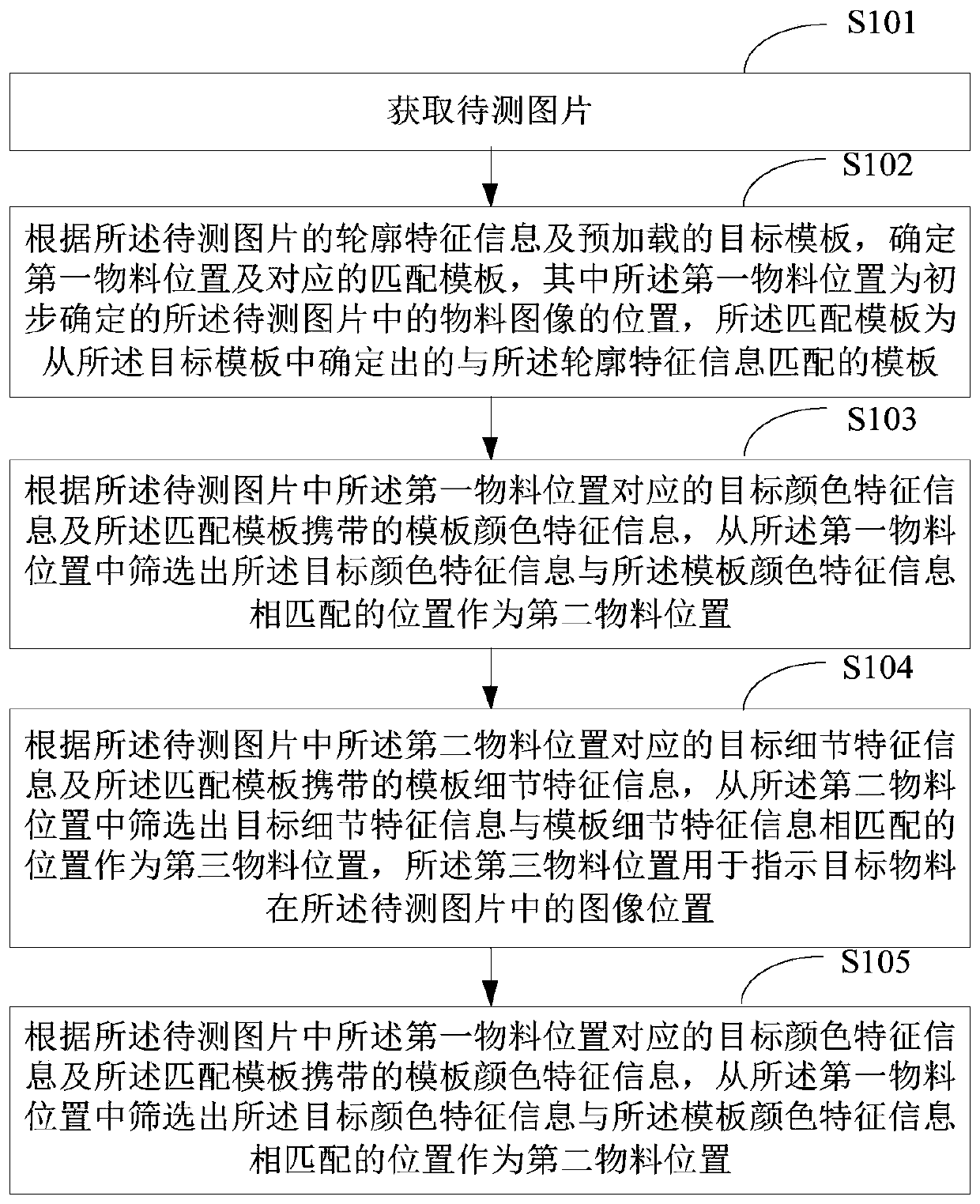
[0036] figure 1 A schematic flow chart of the first material detection method provided in the embodiment of the present application is shown, and the details are as follows:
[0037] In S101, a picture to be tested is acquired.
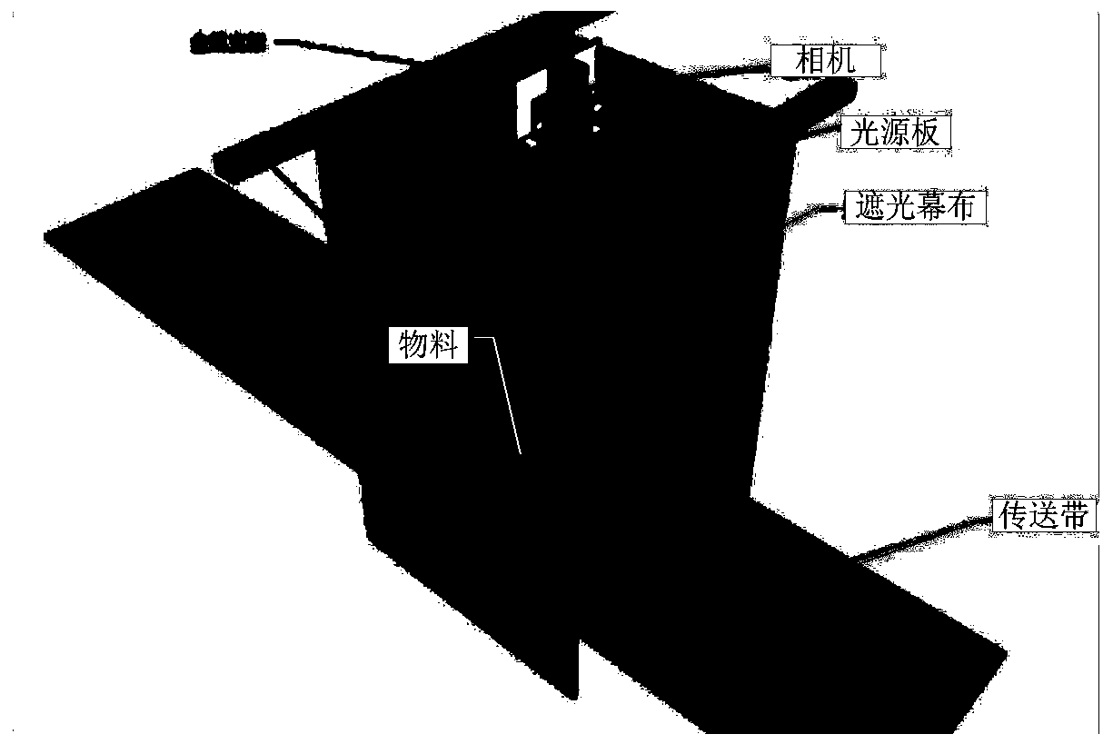
[0038] The picture to be tested in the embodiment of the present application is a picture taken by a camera in a target detection area, and the target detection area may specifically be an area where materials pass through during conveyance. Exemplarily, as figure 2 As shown, a schematic diagram of an application scenario according to the embodiment of the present application is given, wherein the materials are scattered on the transmission belt through a mechanical device, and the area surrounded by the shading curtain in the figure is the target detection area, and the There is a light source board and a camera; when the material reaches the target detection area along with the conveying belt, the camera starts to shoot the target detection area ...
Embodiment 2
[0091] Figure 6 A schematic flowchart of the second material detection method provided by the embodiment of the present application is shown, and the execution subject in the embodiment of the present application is a terminal device. Specifically, this embodiment adds the target template loading step S601 on the basis of the previous embodiment. S602-S606 in the embodiment of the present application are exactly the same as S101-S105 in the previous embodiment. For details, please refer to the previous implementation Relevant descriptions of S101-S105 in the example are not repeated here. Such as Figure 6 Step S601 in the shown material detection method is described in detail as follows:
[0092] In S601, a material table is acquired, and a target template is loaded from pre-built material templates according to the material table.
[0093] The pre-built material templates in the embodiment of the present application are multiple templates constructed and stored in advanc...
Embodiment 3
[0130] Figure 12 It shows a schematic structural diagram of a material detection device provided by the embodiment of the present application. For the convenience of description, only the parts related to the embodiment of the present application are shown:
[0131] The material detection device includes: a picture acquisition unit 121 , a first material position determination unit 122 , a second material position determination unit 123 , a third material position determination unit 124 , and a target material information determination unit 125 . in:
[0132] The picture acquiring unit 121 is configured to acquire the picture to be tested.
[0133] The first material position determination unit 122 is configured to determine the first material position and the corresponding matching template according to the profile feature information of the image to be tested and the preloaded target template, wherein the first material position is the initially determined The position of...
PUM
 Abstract
Description
Claims
Application Information
 - R&D
- Intellectual Property
- Life Sciences
- Materials
- Tech Scout
- Unparalleled Data Quality
- Higher Quality Content
- 60% Fewer Hallucinations
Browse by: Latest US Patents, China's latest patents, Technical Efficacy Thesaurus, Application Domain, Technology Topic, Popular Technical Reports.
© 2025 PatSnap. All rights reserved.Legal|Privacy policy|Modern Slavery Act Transparency Statement|Sitemap|About US| Contact US: help@patsnap.com


