Test probe assembly and test socket

A technology for testing probes and probes, used in electronic circuit testing, measuring electricity, measuring devices, etc., to achieve the effects of easily shielding noise, improving noise shielding efficiency, and improving durability

Pending Publication Date: 2020-06-05
LEENO IND INC
View PDF10 Cites 7 Cited by
  • Summary
  • Abstract
  • Description
  • Claims
  • Application Information

AI Technical Summary

Problems solved by technology

[0005] The object of the present invention is conceived to solve conventional problems and to provide a test probe module for testing radio frequency semiconductors or high speed semiconductors and a test socket with improved noise shielding and easy repair and maintenance

Method used


Image

  • Test probe assembly and test socket
  • Test probe assembly and test socket
  • Test probe assembly and test socket

Examples


no. 1 example

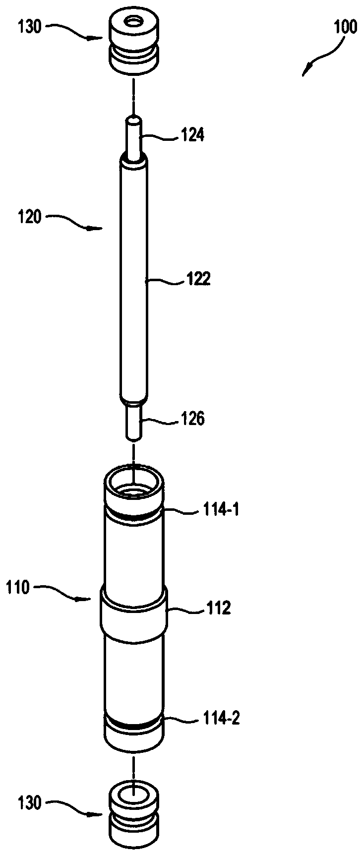
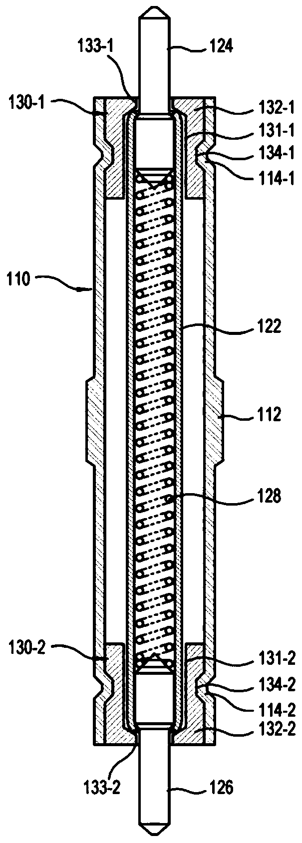
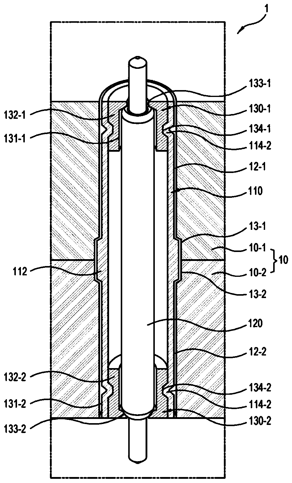
[0042] Such as image 3 As shown in , the tube 110 of the test probe module 100 is filled in the test socket 1 over the entire thickness of the test socket 1 , thereby preventing noise interference between adjacent test probe modules 100 as much as possible. In addition, when a certain test probe module 100 fails or collapses, only the corresponding test probe module 100 can be replaced. That is, according to the first embodiment of the present invention, an insulating support member mounted to the top and bottom surfaces of the conductive block to support the probes is not included.

[0043] Figure 4 and 5 They are respectively cross-sectional views of the test socket 1 to which the test probe module 100 according to the second embodiment and the third embodiment of the present invention is applied. In these examples, with Figure 1 to Figure 3 Parts that are partly the same as those of the illustrated first embodiment are denoted by the same numerals, and redundant desc...


PUM


Abstract

Disclosed is a test probe assembly. The test probe assembly includes: a conductive pipe; a probe inserted in the pipe without contacts and elastically retractable along a lengthwise direction; and aninsulation probe supporting member configured to support the probe between an inner wall of the pipe and an outer surface of the probe. The test probe assembly of the present disclosure is improved innoise shield performance and convenient in repairing the probe since the probe is mounted to a probe socket as supported in a metal pipe without contacts.

Description

technical field [0001] The invention relates to a test probe assembly and a test socket for testing a radio frequency semiconductor or a high-speed semiconductor or similar objects to be tested. Background technique [0002] In a test socket for testing radio frequency semiconductors or high speed semiconductors, signal probes are non-contact mounted to conductive blocks to shield noise from adjacent signal probes. In this case, the opposite end portions included in the signal probe are supported on insulating support plates arranged on both sides of the conductive block after the signal probe passes through the conductive block in a non-contact manner. superior. However, for this conventional method, it is difficult to support the probes when the insulating support plate is not thick enough to support the probes. On the other hand, when the insulating support plate is thick, the support plate causes a problem of noise leakage between the signal probes. [0003] To solve ...

Claims


Application Information

Patent Timeline
Patent Type & Authority Applications(China)
IPC IPC(8): G01R1/067G01R1/18G01R3/00G01R1/04G01R31/28
CPCG01R1/06722G01R1/06772G01R1/18G01R3/00G01R1/0466G01R1/045G01R1/0441G01R1/06733G01R31/2886
Inventor 郑宰欢金勤洙申晶澈
Owner LEENO IND INC
Why Eureka
Try Eureka