Cleaning tool

A technology for cleaning tools and cleaning surfaces, applied in cleaning equipment, cleaning machinery, carpet cleaning, etc., can solve the problems of affecting cleaning effect and secondary pollution, and achieve the effects of guaranteed cleaning effect, high practicability, and wide application range

Pending Publication Date: 2020-06-09
SHENZHEN POLYTECHNIC
View PDF0 Cites 4 Cited by
  • Summary
  • Abstract
  • Description
  • Claims
  • Application Information

AI Technical Summary

Problems solved by technology

[0005] To sum up, in order to ensure the cleaning quality, it is necessary to wet the mop on the manual mop or mopping robot, so that a certain amount of water is absorbed on the mop. figure 1 As shown, when the mop moves in one direction ( figure 1 Left picture), the water on the mop will not form secondary pollution in the cleaned area; while the mop is reciprocating ( figure 1 Right picture), the water on the mop will be brought into the cleaned area, thus forming secondary pollution of the cleaned area and affecting the cleaning effect

Method used


Image

  • Cleaning tool
  • Cleaning tool
  • Cleaning tool

Examples


Embodiment 1

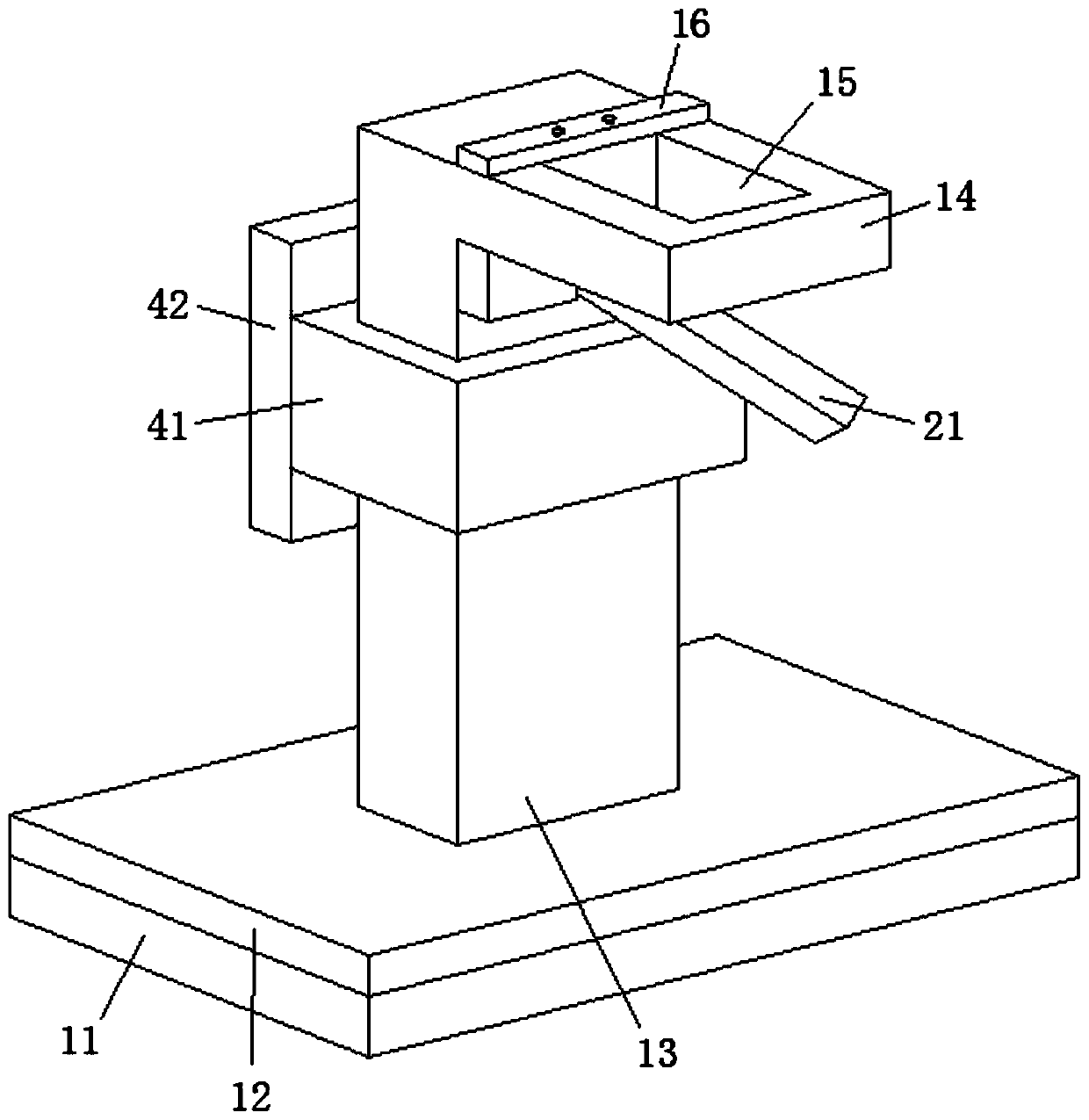
[0073] see Figure 11 As shown, the above-mentioned disclosed cleaning tool is installed in the housing (i.e. the structure shown in the dotted frame in the figure), and then a hand-held push rod is installed on the top of the housing.

[0074] Specifically, when in use, the hand-held push rod is used to push the cleaning tool to perform frictional cleaning of the cleaning surface. The cleaning surface mentioned here includes not only the ground, but also walls and the like.

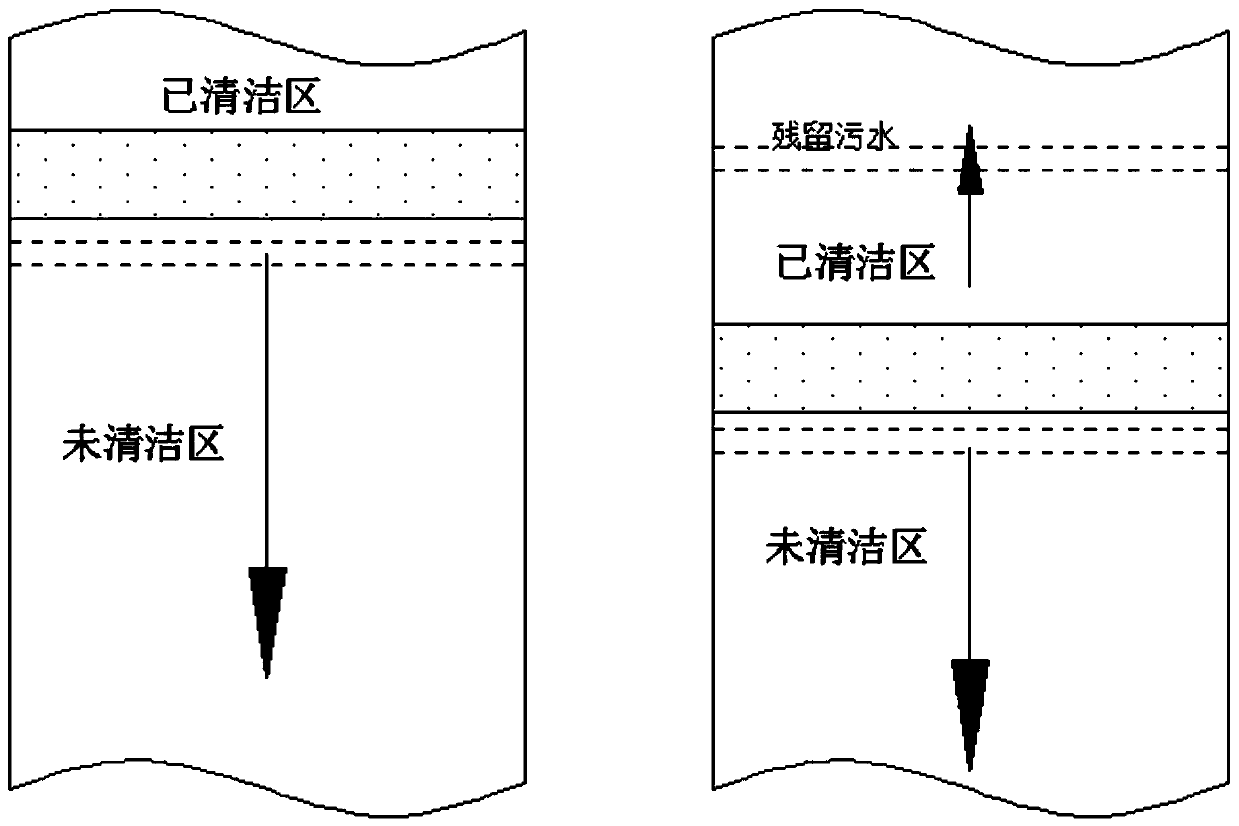
[0075] It is easy to explain that the use method of this embodiment is the same as that of the existing manual mop, and the user does not need to deliberately change the operation habit of dragging the mop back and forth to avoid the problem of residual sewage.

Embodiment 2

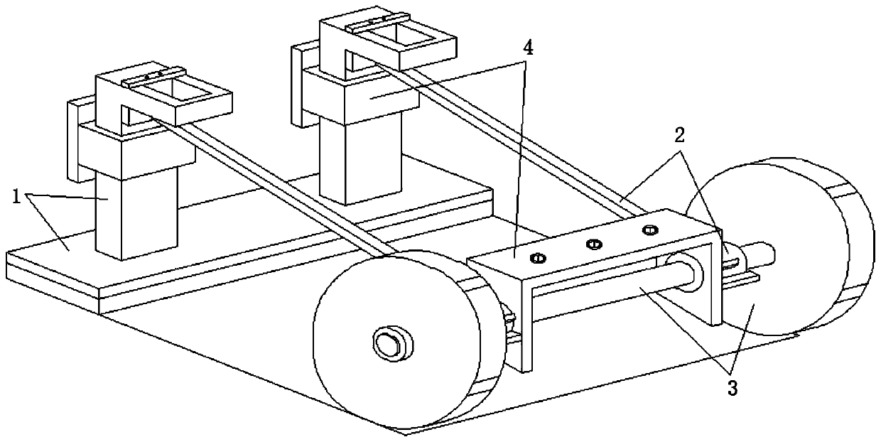
[0077] see Figure 12-Figure 13 As shown, the above-mentioned disclosed cleaning tool is installed in the housing (i.e. the structure shown in the dotted frame in the figure), and the mobile drive assembly 6 is also installed in the housing to cooperate with the mobile assembly 3 to realize the automatic movement of the cleaning tool.

[0078] Specifically, in this embodiment, refer to Figure 13 Regarding the mobile drive assembly 6, the driving motor and the driving group gear can be used in the form that the driving group gear is installed on the rotating shaft 31, and the driving group gear is driven by the driving motor to rotate, thereby realizing the driving of the rotating shaft 31 and other structures.

[0079] In summary, in the above state, the integral cleaning tool constitutes an automatic cleaning tool.

[0080] In addition, in this embodiment, a steering drive assembly is also installed at the bottom of the housing, refer to Figure 12 As for the steering driv...


PUM


Abstract

The invention belongs to the technical field of cleaning tools, and discloses a cleaning tool. The cleaning tool comprises: a moving assembly used for achieving movement of the whole cleaning tool; alifting mop assembly used for achieving friction cleaning of a cleaning face in the moving process; a linkage assembly used for connecting the moving assembly and the lifting mop assembly, wherein when the moving assembly moves forwards, the lifting mop assembly is limited to be in contact with the cleaning surface, and when the moving assembly retreats, the lifting mop assembly is lifted in a linkage mode, and the lifting mop assembly is limited to be separated from the cleaning surface; and a mounting assembly comprising a second mounting part and used for limiting the linkage assembly to perform linkage on retreating of the moving assembly and lifting of the lifting mop assembly within a limited range. In conclusion, it can be effectively guaranteed that the mop cloth is separated fromthe cleaning surface when the tool retreats, so that water on the mop cloth is prevented from remaining in a cleaned area, and the cleaning effect is improved; and when the limit range is exceeded, the continuous retreating of the tool is not interfered.

Description

technical field [0001] The invention belongs to the technical field of cleaning tools, and in particular relates to a cleaning tool. Background technique [0002] At present, the existing cleaning tools mainly include two kinds of manual cleaning tools and electric cleaning tools, wherein: [0003] Manual cleaning tools are operated by people. Taking manual mop as an example, the usual way for people to mop the floor is to reciprocate with a hand-held mop, so that the mop reciprocates against the ground, so as to achieve the effect of cleaning the ground; [0004] The electric cleaning tool is automatic cleaning. Take the floor mopping robot as an example. The floor mopping robot automatically plans the route and moves on the ground along the planned route to rub the ground to form a clean; and once the mopping robot encounters obstacles, it will Obstacles need to be avoided, and it is unavoidable to perform backward or turning operations during the obstacle avoidance proce...

Claims


Application Information

Patent Timeline
Patent Type & Authority Applications(China)
IPC IPC(8): A47L11/28A47L11/40
CPCA47L11/28A47L11/40A47L11/4055
Inventor 闵光培姜琳
Owner SHENZHEN POLYTECHNIC
Why Eureka
Try Eureka