A mirror group fixture for precision testing of CNC machine tools
A mirror group, precision detection technology, applied in the fields of testing instruments and mechanical manufacturing design, can solve problems such as low adjustment efficiency and precision, unfavorable industrial automation, etc., and achieve the effect of reducing clamping errors and facilitating detection and identification.
- Summary
- Abstract
- Description
- Claims
- Application Information
AI Technical Summary
Problems solved by technology
Method used
Image

Examples
Embodiment 1
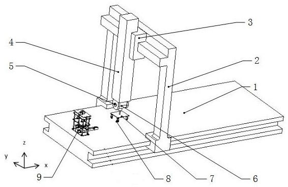
[0027] The present invention is realized through the following technical solutions, as Figure 1-Figure 6 As shown, a mirror group fixture 7 for precision testing of a CNC machine tool includes a machine bed 1, a moving unit 2 installed on the machine bed 1, a swing unit installed on the side of the moving unit 2 close to the machine bed 1, And the mirror group unit installed on the side of the swing unit close to the machine bed 1; the mirror group unit includes a mirror group fixture 7 connected to the swing unit, and a mirror 8 installed on the mirror group fixture 7.
[0028] It should be noted that, through the above improvements, the mobile unit 2 can move relative to the machine bed 1 in the X-axis direction, the Y-axis direction and the Z-axis direction; since the mobile unit 2 is connected with the mirror group unit through the swing unit, thus By controlling the movement of the moving unit 2, the movement of the mirror group unit is realized; the swing unit performs ...
Embodiment 2
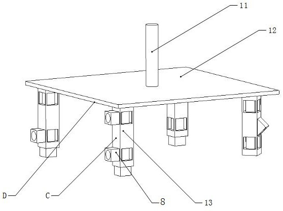
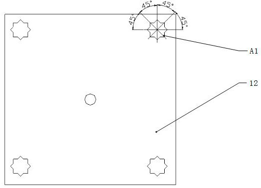
[0030] This embodiment is further optimized on the basis of the above embodiments, such as figure 2 As shown, further, in order to better realize the present invention, the mirror group fixture 7 includes a clamping rod 11 connected to the swing unit, a mounting plate 12 installed on the side of the clamping rod 11 away from the swing unit, and mounted on The mounting plate 12 is away from the side of the clamping rod 11 and is used for mounting the reflector group mounting post 13 of the reflector 8 .
[0031] Further, in order to better realize the present invention, Figure 4 As shown, the side of the mirror group mounting post 13 away from the mounting plate 12 is provided with a first mounting groove B1, and the surrounding sides of the mirror group mounting post 13 are provided with a second mounting groove B2 and a third mounting groove B3 ; The bottom of the second mounting groove B2 is arranged parallel to the side of the mirror group mounting column 13, the third m...
Embodiment 3
[0042] This embodiment is further optimized on the basis of the above embodiments, such as figure 1 As shown, further, in order to better realize the present invention, the number of the mirror group mounting posts 13 is four and they are evenly mounted on the side of the mounting plate 12 away from the clamping rod 11 .
[0043] Further, in order to better realize the present invention, the moving unit 2 includes two X-axis moving support frames that are perpendicular to the side of the machine bed 1 near the mirror group unit and are slidably connected with the machine bed 1. The connecting rod 4 between the X-axis moving support frames and the Z-axis supporting frame slidingly installed on the connecting rod 4 and moving along the Y-axis direction; the two X-axis moving supporting frames are arranged in parallel.
[0044] Further, in order to better realize the present invention, the Z-axis support frame includes a slider 3 that is slidably installed on the connecting rod 4...
PUM
 Abstract
Description
Claims
Application Information
 - R&D
- Intellectual Property
- Life Sciences
- Materials
- Tech Scout
- Unparalleled Data Quality
- Higher Quality Content
- 60% Fewer Hallucinations
Browse by: Latest US Patents, China's latest patents, Technical Efficacy Thesaurus, Application Domain, Technology Topic, Popular Technical Reports.
© 2025 PatSnap. All rights reserved.Legal|Privacy policy|Modern Slavery Act Transparency Statement|Sitemap|About US| Contact US: help@patsnap.com