Fixing device of main transmission shaft of spinning machine

A main drive shaft and fixing device technology, applied in couplings, mechanical equipment, rigid shaft couplings, etc., can solve the problems of increased vibration value of the laying machine, de-soldering, hidden troubles, etc., and achieve the overall structural design. Ingenious, reduce frequent replacement, easy to prevent loose effect

Inactive Publication Date: 2015-12-23
JIANGSU YONGGANG GROUP CO LTD
View PDF11 Cites 2 Cited by
  • Summary
  • Abstract
  • Description
  • Claims
  • Application Information

AI Technical Summary

Problems solved by technology

The connection between the main drive shaft of the laying machine and the flange is fixed by electric welding on both sides. After being used online for a period of time, cracks and peeling will appear in the joint between the main drive shaft of the laying machine and the flange. Welding phenomenon, causing the vibration value of the laying machine to increase during operation, there are certain hidden dangers of failure, which threaten the safety of equipment operation, and cause the main drive shaft of the laying machine to be replaced with a new shaft every time it goes offline, resulting in unnecessary waste. Moreover, it affects the transmission stability of the laying head. In order to solve this technical problem, those skilled in the art are also constantly trying, such as adding new fixed equipment, etc. These methods have high cost and complex structure, and have not fundamentally solved this technology. problem, therefore, for the existing problems in the prior art, there is an urgent need for a new technical solution to solve the above technical problems

Method used


Image

  • Fixing device of main transmission shaft of spinning machine
  • Fixing device of main transmission shaft of spinning machine
  • Fixing device of main transmission shaft of spinning machine

Examples


Embodiment 1

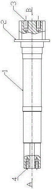
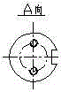
[0026] see figure 1 , diagram 2-1 , Figure 2-2 , Figure 5 , a main transmission shaft fixing device for a laying machine, the fixing device includes a main transmission shaft 1, a flange 5, a screw umbrella 6, and the flange 5 is arranged on the main transmission shaft 1, and the screw umbrella 6 is set On the flange 5 , a cylindrical pin 12 is arranged on the screw umbrella 6 and the flange 5 . The fixing device can adapt to the stable rolling requirements of the main drive shaft of the high-speed wire laying machine, overcomes the phenomenon of desoldering and cracking caused by the connection between the main drive shaft of the laying machine and the flange plate, and reduces the cost of the laying machine. The vibration value during operation avoids frequent replacement of the main drive shaft, thereby ensuring the safe operation of the equipment and reducing production costs.

Embodiment 2

[0028] see figure 1 , Figure 5 , as an improvement of the present invention, the fixing device further includes an annular rib 2, and the annular rib 2 is arranged on the main transmission shaft 1, which facilitates the positioning of the flange. The length of the entire main transmission shaft remains unchanged, and the annular rib is close to the flange, which ensures that one side of the main transmission shaft is fixed. The rest of the structures and advantages are exactly the same as in Embodiment 1.

Embodiment 3

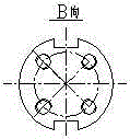
[0030] see figure 1 , image 3 , Figure 5 , as an improvement of the present invention, the fixing device further includes a main transmission shaft pressure plate 7, the main transmission shaft pressure plate 7 is arranged on the main transmission shaft 1 and the flange 5, and is fixed by pressure plate bolts 9. The rest of the structures and advantages are exactly the same as in Embodiment 1.


PUM


Abstract

The invention relates to a fixing device of a main transmission shaft of a spinning machine. The fixing device is characterized in that the fixing device comprises the main transmission shaft, a flange and a screw umbrella, the flange is arranged on the main transmission shaft, the screw umbrella is arranged on the flange, and cylindrical pins are arranged on the screw umbrella and the flange. The fixing device is ingenious in overall design and compact in structure and overcomes the defects of a fixing device in the prior art. According to the fixing device, the phenomenon that due to the fact that the main transmission shaft and the flange of the spinning machine are fixed through burning electric soldering, cracks are caused is avoided. The transmission failure of the main transmission shaft of the spinning machine is prevented. The replacing frequency of the main transmission shaft of the spinning machine is reduced, transmission stability of the main transmission shaft is guaranteed, and production cost is reduced.

Description

technical field [0001] The invention relates to a fixing device, in particular to a fixing device for a main drive shaft of a laying machine, and belongs to the technical field of laying machine equipment. Background technique [0002] The wire laying machine is the key equipment for spinning the rolled wire into coils for collection in the production of high-speed wire rods. In the prior art, many domestic high-end wire factories use the Xihang wire laying machine to roll high-speed wire rods. The laying head is one of the core equipments of high-speed wire rod mills, and the vibration of the laying head directly affects the production efficiency of high-speed wire rods. The connection between the main drive shaft of the laying machine and the flange is fixed by butt welding on both sides. After a period of online use, cracks and peeling will occur at the joint between the main drive shaft of the laying machine and the flange. The phenomenon of welding causes the vibration...

Claims


Application Information

Patent Timeline
Patent Type & Authority Applications(China)
IPC IPC(8): F16D1/06B21B41/00
Inventor 陈荣军卞云蕾徐明振
Owner JIANGSU YONGGANG GROUP CO LTD
Why Eureka
Try Eureka