A deburring positioning device and its use method

A technology for positioning device and burr removal, which is applied in the direction of grinding drive device, grinding/polishing safety device, machine tools suitable for grinding the edge of workpiece, etc., which can solve the problem of increasing the cost and weight of grinding positioning device and increasing the complexity of grinding positioning device problems such as increasing the damage rate of the grinding and positioning device, etc., to achieve the effect of strengthening the connection and locking, simplifying the structure, and reducing the structure

Active Publication Date: 2021-03-12
CHONGQING IND POLYTECHNIC COLLEGE
View PDF5 Cites 0 Cited by
  • Summary
  • Abstract
  • Description
  • Claims
  • Application Information

AI Technical Summary

Problems solved by technology

In the existing deburring, the parts to be repaired are positioned manually, and then the deburring is performed by hand-held burr brushes. On the one hand, the clamping stability of the parts to be repaired by the fixture is not high, so that the The repair effect is not good during repair; on the other hand, the labor intensity of the operator is high, and the work efficiency is not good; on the other hand, there is a certain risk of injury when the burr is removed by direct positioning by hand
[0003] Most of the existing grinding and fixing devices use screw or chain transmission. Whether it is through screw, chain or gear transmission, it is necessary to overcome the friction between steel and steel. The strength of the staff is not enough to overcome this friction. Therefore, it is necessary to use a motor or cylinder as a The power source can be overcome, which increases the complexity of the grinding positioning device
Use the motor or cylinder as the power source to realize the lifting and positioning of the fixed object, which increases the cost and weight of the grinding and positioning device, which is not easy to promote and carry. At the same time, because of the complexity of the power source, the damage rate of the grinding and positioning device is increased.

Method used


Image

  • A deburring positioning device and its use method
  • A deburring positioning device and its use method
  • A deburring positioning device and its use method

Examples


Embodiment Construction

[0044] Below in conjunction with accompanying drawing and embodiment the present invention will be further described:

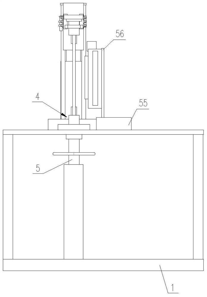
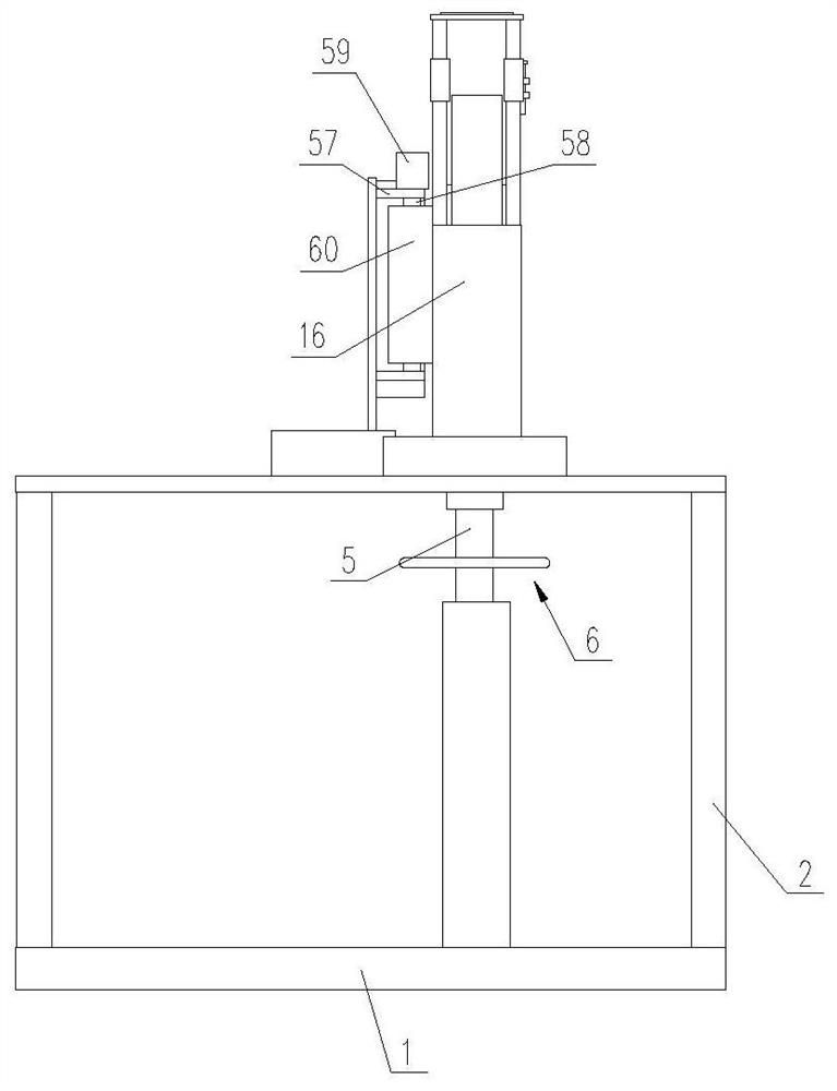
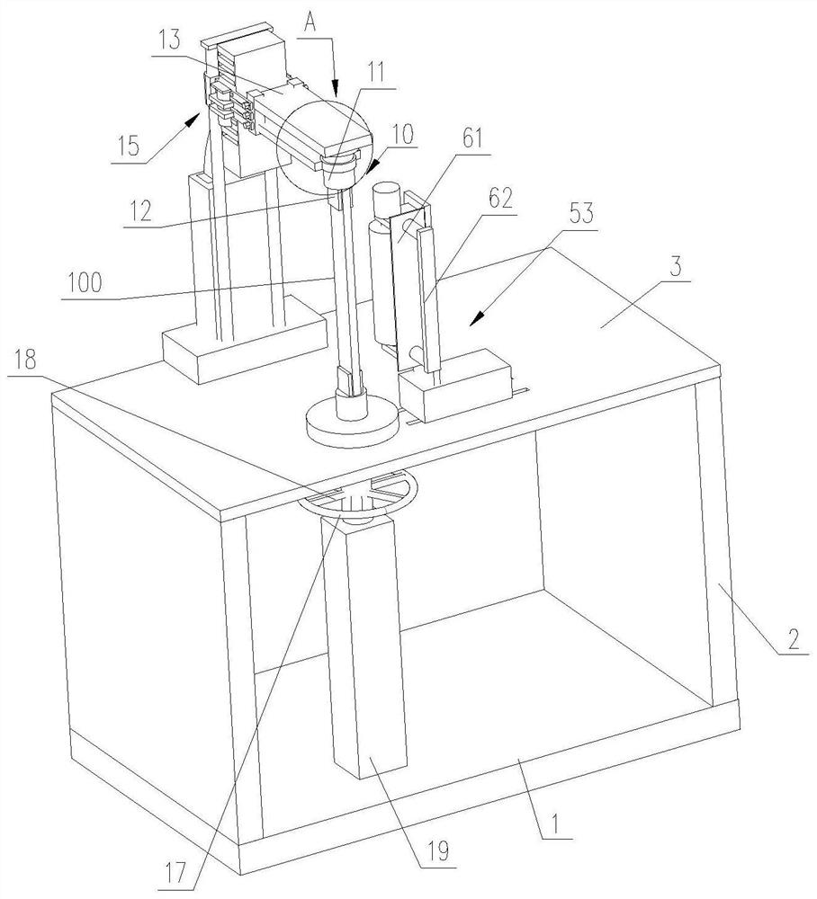
[0045] Such as Figure 1 to Figure 11 As shown, a burr removal and positioning device includes a base 1, and two support plates 2 are arranged on the base 1, and the upper ends of each support plate 2 are connected by a workbench 3;

[0046] The worktable 3 is provided with a first positioning unit 4, the first positioning unit 4 includes a first rotating shaft 5, the first rotating shaft 5 rotatably passes through the workbench 3, and the bottom of the workbench 3 A rotating handle 6 is provided; the upper end of the first rotating shaft 5 is connected to the lower end of the first clamping seat 7, and the upper end of the first clamping seat 7 is provided with a first positioning groove 8 and two first limit blocks 9, The first positioning groove 8 is located between the two first limiting blocks 9;

[0047]A second positioning unit 10 used in conjunction...


PUM


Abstract

The invention discloses a burr removing and positioning device. The burr removing and positioning device comprises a base; two supporting plates are arranged on the base; the upper ends of the supporting plates are connected through a worktable; a first positioning unit is arranged on the worktable; the first positioning unit comprises a first rotating shaft; the first rotating shaft rotatably passes through the worktable; a rotating handle is arranged below the worktable; the first positioning groove is located between two first limiting blocks; the upper end of a second clamping seat is rotatably connected with a top plate; the rear end of the top plate is connected with a fixed seat through an adjustment unit; and the fixed seat is connected with the base. The efficiency is improved through the use in cooperation with a polishing unit, a protective plate is arranged on the polishing unit, an operator holds a ring below the worktable with one hand, and holds the handle above the worktable with the other hand, thereby effectively avoiding injury to the operator's finger in burr removing. In addition, a part to be polished is positioned by the burr removing and positioning device,and the manual positioning is replaced, so that the labor intensity of the operator's finger is effectively reduced.

Description

technical field [0001] The present invention relates to a positioning device, in particular to a positioning device for burr removal and its usage method. Background technique [0002] Deburring, after the parts are processed and manufactured, the burrs on the parts need to be removed, and the burrs are the thorns or flashes formed on the parts. In the existing deburring, the parts to be repaired are positioned manually, and then the deburring is performed by hand-held burr brushes. On the one hand, the clamping stability of the parts to be repaired by the fixture is not high, so that the The repair effect is not good during repair; on the other hand, the labor intensity of the operator is high, and the work efficiency is not good; on the other hand, there is a certain risk of injury when the burr is removed by direct hand positioning. [0003] Most of the existing grinding and fixing devices use screw or chain transmission. Whether it is through screw, chain or gear transm...

Claims


Application Information

Patent Timeline
Patent Type & Authority Patents(China)
IPC IPC(8): B24B9/00B24B41/06B24B41/02B24B55/00B24B47/12B24B1/00
CPCB24B1/00B24B9/00B24B41/02B24B41/06B24B47/12B24B55/00
Inventor 李亚美
Owner CHONGQING IND POLYTECHNIC COLLEGE
Why Eureka
Try Eureka