Mechanical arm clamp for motor rotor production

A technology for motor rotors and manipulators, applied in manipulators, program-controlled manipulators, manufacturing stator/rotor bodies, etc., can solve problems affecting product quality, high labor intensity of workers, many processing and assembly processes, etc., to facilitate the operation of workers , Reduce the labor intensity of workers, reduce the effect of labor costs

Pending Publication Date: 2020-06-09
浙江精力工具有限公司
View PDF9 Cites 1 Cited by
  • Summary
  • Abstract
  • Description
  • Claims
  • Application Information

AI Technical Summary

Problems solved by technology

[0002] In the production process of the motor rotor, due to the complex structure of the motor rotor, there are many processing procedures and assembly procedures, and the requirements for processing accuracy and assembly accuracy are relatively high, each process requires workers to operate, the labor intensity of the workers is high, and the labor cost is high. Moreover, there are many assembly errors, which affect product quality;
[0003] At present, some manufacturers use manipulators to assist workers in the operation, because the structure of the motor rotor is relatively complicated, and there are many processing procedures and assembly procedures (not only need to move back and forth, left, right, up and down and rotate, but also need to carry out the process of independent rotation of the jaws), therefore, need Design a special fixture to cooperate with the manipulator to operate

Method used


Image

  • Mechanical arm clamp for motor rotor production
  • Mechanical arm clamp for motor rotor production

Examples


Embodiment 1

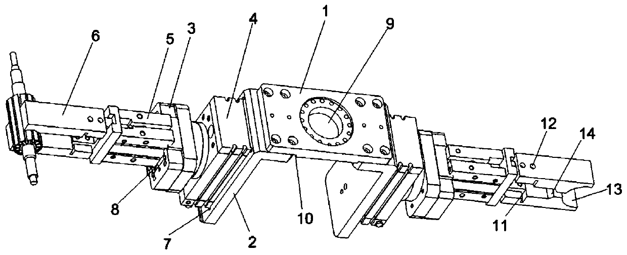
[0027] Such as figure 1 As shown, a manipulator fixture for motor rotor production includes a rotating connecting plate 1 and a rotor clamping structure installed symmetrically at both ends of the rotating connecting plate 1. The rotor clamping structure includes clamping jaws 6, driving jaws 6 for clamping and loosening The pneumatic finger 5 and the rotating cylinder 4 that drives the pneumatic finger 5 to rotate, the pneumatic finger 5 is installed on the rotating cylinder 4 through the fixed plate 3, and the rotating cylinder 4 is installed on the rotating connecting plate 1 through the mounting plate 2. The mounting plate 2 is L-shaped, and the top of the short side of the mounting plate 2 is fixed on the bottom of the rotating connecting plate 1 , and the rotary cylinder 4 is fixed on the outside of the long side of the mounting plate 2 . The outside of the long side of the mounting plate 2 is provided with a rotary cylinder mounting groove 7 matching the rotary cylinder...

Embodiment 2

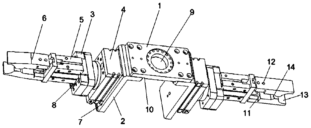
[0029] Such as figure 2 As shown, the front end of the outer surface of one side of the jaw 6 is inclined, and the middle part of the inner surface is provided with a limit step 14, while the outer surface of the other side of the jaw 6 is flat, and the middle part of the inner surface is provided with a limit step 14.

Embodiment 3

[0031] The jaws on both sides are all flat on the outside, and the middle part on the inside is flat.


PUM


Abstract

The invention relates to a part of motor production equipment, in particular to a mechanical arm clamp for motor rotor production. The mechanical arm clamp for motor rotor production comprises a rotating connecting plate and rotor clamping structures symmetrically mounted on the two ends of the rotating connecting plate, the rotor clamping structures comprise clamping claws, pneumatic fingers usedfor driving the clamping claws to be clamped or loosened and rotating air cylinders used for driving the pneumatic fingers to rotate, the pneumatic fingers are mounted on the rotating air cylinders through fixed plates, and the rotating air cylinders are mounted on the rotating connecting plate through mounting plates. The clamp is assembled with a mechanical arm through the rotating connecting plate, the clamp can carry out front, back, left, right, up and down moving and rotating in cooperation with the mechanical arm, the mechanical arm can conveniently assist a worker for operation, manual cost is reduced, labor intensity of the worker is reduced, product quality is ensured, meanwhile, the rotating air cylinders are adopted to drive the clamping claws to rotate, the clamping claws canindependently rotate, and different procedure needs during motor rotor machining and assembling can be met.

Description

technical field [0001] The invention relates to a component of a motor production equipment, in particular to a manipulator clamp for the production of a motor rotor. Background technique [0002] In the production process of the motor rotor, due to the complex structure of the motor rotor, there are many processing procedures and assembly procedures, and the requirements for processing accuracy and assembly accuracy are relatively high, each process requires workers to operate, the labor intensity of the workers is high, and the labor cost is high. Moreover, there are many assembly errors, which affect product quality; [0003] At present, some manufacturers use manipulators to assist workers in the operation, because the structure of the motor rotor is relatively complicated, and there are many processing procedures and assembly procedures (not only need to move back and forth, left, right, up and down and rotate, but also need to carry out the process of independent rotat...

Claims


Application Information

Patent Timeline
Patent Type & Authority Applications(China)
IPC IPC(8): B25J15/00B25J9/14H02K15/02
CPCB25J15/0052B25J9/146H02K15/02
Inventor 胡靖铭陈韬池海
Owner 浙江精力工具有限公司
Why Eureka
Try Eureka