Feeding device for silicon wafer processing

A silicon wafer and mounting port technology is applied in the field of feeding devices for silicon wafer processing, which can solve the problems of silicon wafer breakage and hard extrusion, and avoid hard extrusion, structural damage, and excessive initial contact force. Effect

Inactive Publication Date: 2020-06-09
张利红
View PDF7 Cites 5 Cited by
  • Summary
  • Abstract
  • Description
  • Claims
  • Application Information

AI Technical Summary

Problems solved by technology

There are some deficiencies in the above patents: it is easy to produce hard extrusion during the adsorption of silicon wafers, which will cause damage to the silicon wafers

Method used


Image

  • Feeding device for silicon wafer processing
  • Feeding device for silicon wafer processing
  • Feeding device for silicon wafer processing

Examples


Embodiment 1

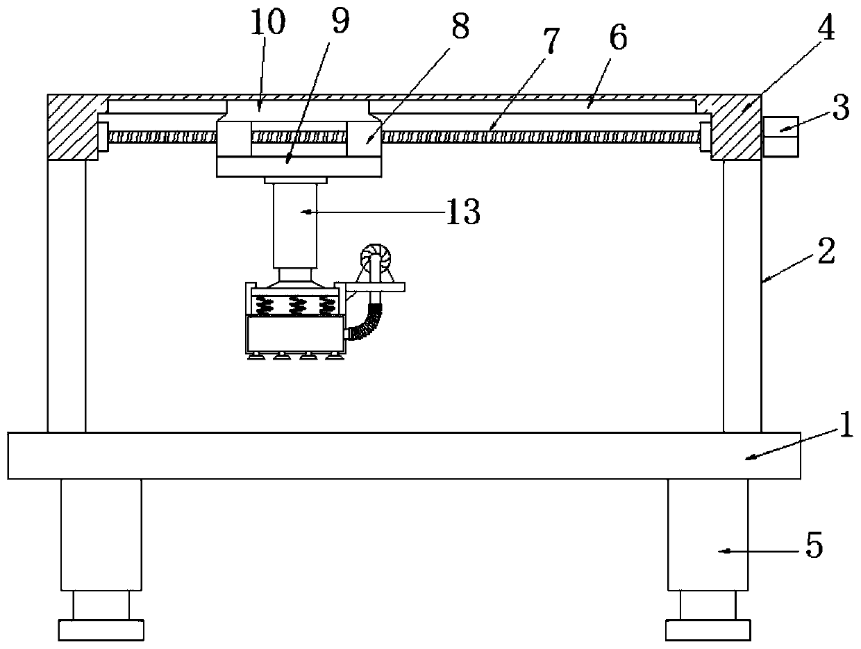
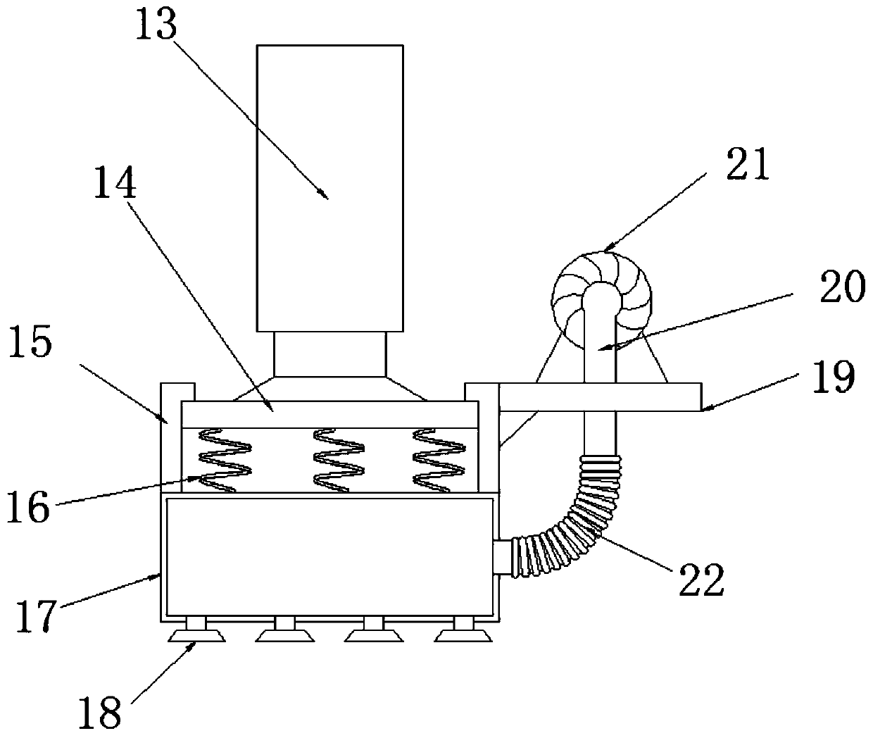
[0024] refer to figure 1 and figure 2 , a feeding device for silicon wafer processing, including a base 1, support rods 2 are fixed on both sides of the top outer wall of the base 1, and the same top plate 4 is fixed on the top of the two support rods 2, and the bottom outer wall of the top plate 4 is opened There is an installation port, and the same screw rod 7 is installed on the inner wall on both sides of the installation port. One end of the screw rod 7 is connected to the driving mechanism. Sliders 8 are fixed on both sides of the bottom outer wall of the guide block 10, and the two sliders 8 are threadedly socketed on the screw rod 7, and the bottom of the two sliders 8 is fixed with the same connecting plate 9, and the bottom outer wall of the connecting plate 9 is fixed with a telescopic rod 13, and the bottom end of the extension rod of the telescopic rod 13 is fixed with a fixed plate 14, the bottom of the fixed plate 14 is fixed with an adsorption mechanism, and...

Embodiment 2

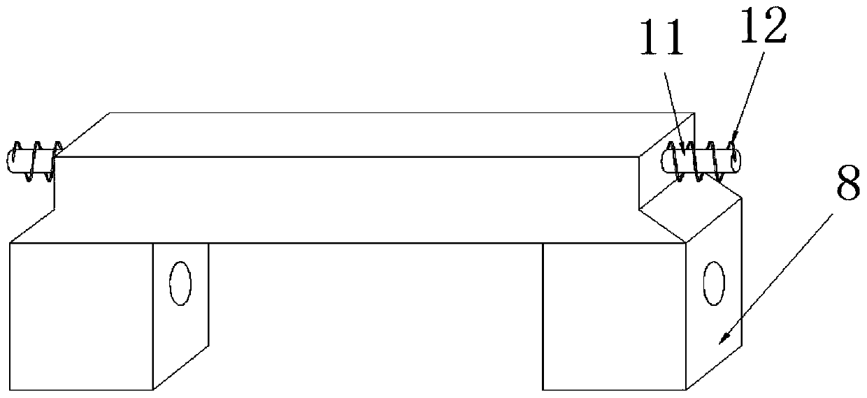
[0028] refer to image 3 , a feeding device for silicon wafer processing. The difference between this embodiment and Embodiment 1 is that the outer walls of both ends of the guide block 10 are also fixed with plug posts 11, and the plug posts 11 are sleeved with buffer springs 12. 1. One end of the buffer spring 12 is fixedly connected with the guide block 10, and the inner walls of the opposite sides of the guide groove 6 are provided with inserting column grooves matching the specification of the inserting column 11.

[0029] The working principle of this embodiment: the insertion column 11 can move laterally synchronously with the guide block 10, when the guide block 10 moves to both ends of the guide groove 6, the insertion column 11 is inserted into the insertion column groove, and the buffer spring 12 gradually Compressed, the reaction force of the buffer spring 12 can protect and buffer the guide block 10, avoiding the hard extrusion of the guide block 10 and the inner ...


PUM


Abstract

The invention discloses a feeding device for silicon wafer processing. The feeding device comprises a base table, supporting rods are fixedly arranged on the two sides of the outer wall of the top ofthe base table, the same top plate is fixedly arranged on the top ends of the two supporting rods, a mounting opening is formed in the outer wall of the bottom of the top plate, the same screw rod isrotationally mounted on the inner walls of the two opposite sides of the mounting opening, a driving mechanism is in transmission connection with one end of the screw rod, a guide groove is formed inthe inner wall of the top of the mounting opening, a guide block is inserted into the guide groove in a sliding mode, sliding blocks are fixedly arranged on the two sides of the outer wall of the bottom of the guide block, the two sliding blocks sleeve the screw rod in a threaded mode, the same connecting plate is fixedly arranged on the bottoms of the two sliding blocks, a telescopic rod is fixedly arranged on the outer wall of the bottom of the connecting plate, a fixing plate is fixedly arranged on the bottom end of an extension rod of the telescopic rod, an adsorption mechanism is fixedlyarranged on the bottom of the fixing plate, and a plurality of compression springs distributed at equal intervals are fixedly arranged between the outer wall of the top of the adsorption mechanism andthe fixing plate. According to the feeding device for silicon wafer processing, the initial contact force between a sucker and the silicon wafer is prevented from being too large, so that the extrusion force is reduced, and the silicon wafer protection capability is improved.

Description

technical field [0001] The invention relates to the technical field of silicon wafer feeding equipment, in particular to a feeding device for silicon wafer processing. Background technique [0002] Silicon is also a very common element, and silicon wafers are sheet-shaped silicon substances formed after a series of processing of silicon elements, which are widely used in various fields, and in the production and processing of silicon wafers, it is necessary to convert silicon The film is taken out from the box for loading, so as to meet the subsequent production needs. [0003] After searching, the Chinese patent application number is CN208000899U, which discloses a feeding mechanism for silicon wafer processing, including a cross bar, the surface of the cross bar is provided with a guide rail, and the surface of the guide rail is rollingly connected with a mounting plate, and the mounting plate The inner surface wall is welded with a clamping plate, and the inner surface w...

Claims


Application Information

Patent Timeline
Patent Type & Authority Applications(China)
IPC IPC(8): B65G47/91
CPCB65G47/91
Inventor 张利红
Owner 张利红
Why Eureka
Try Eureka