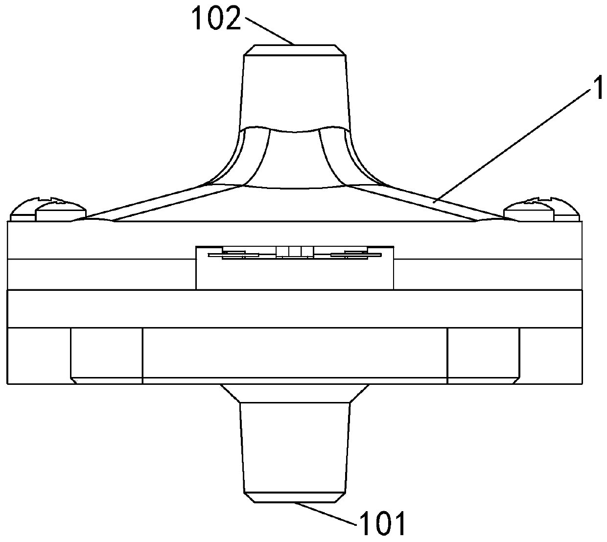
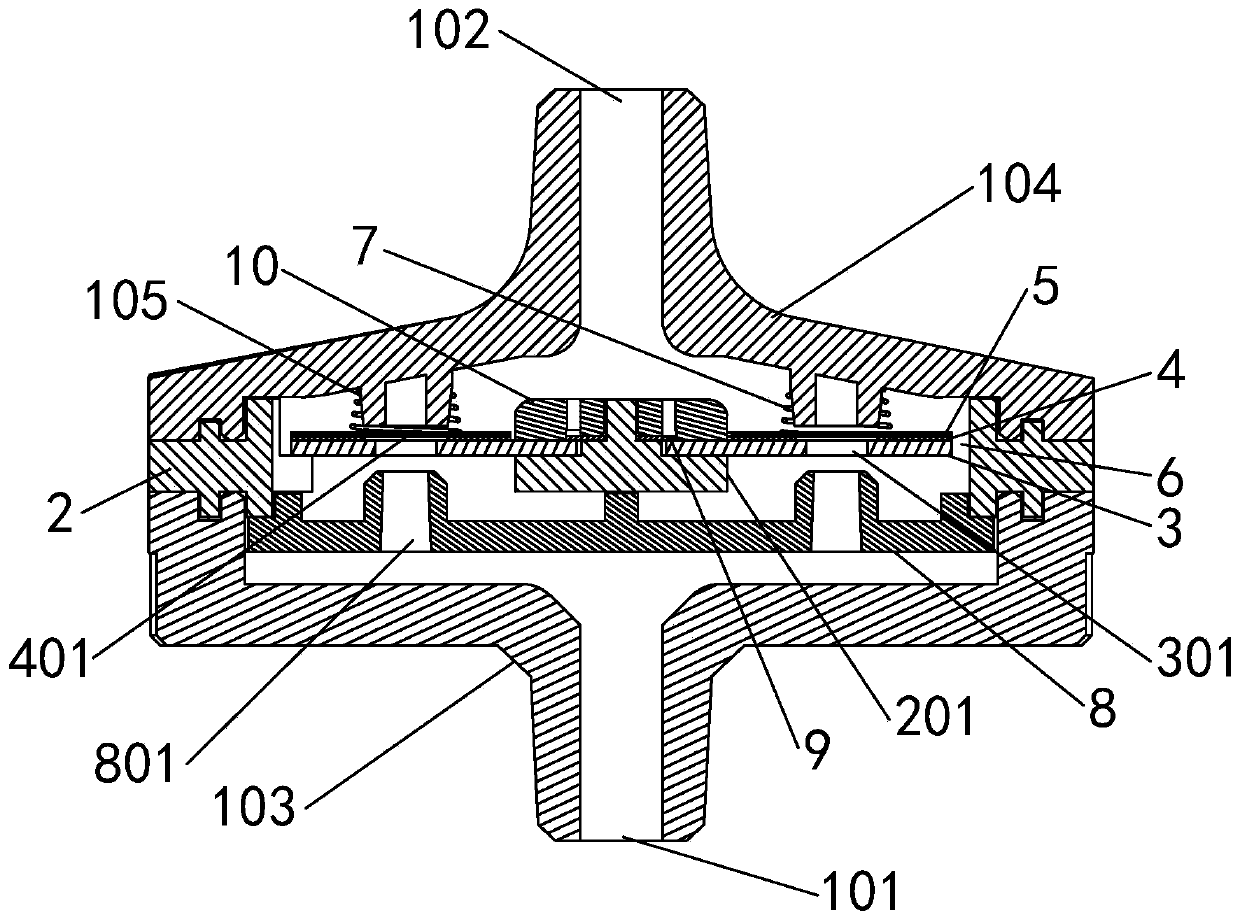
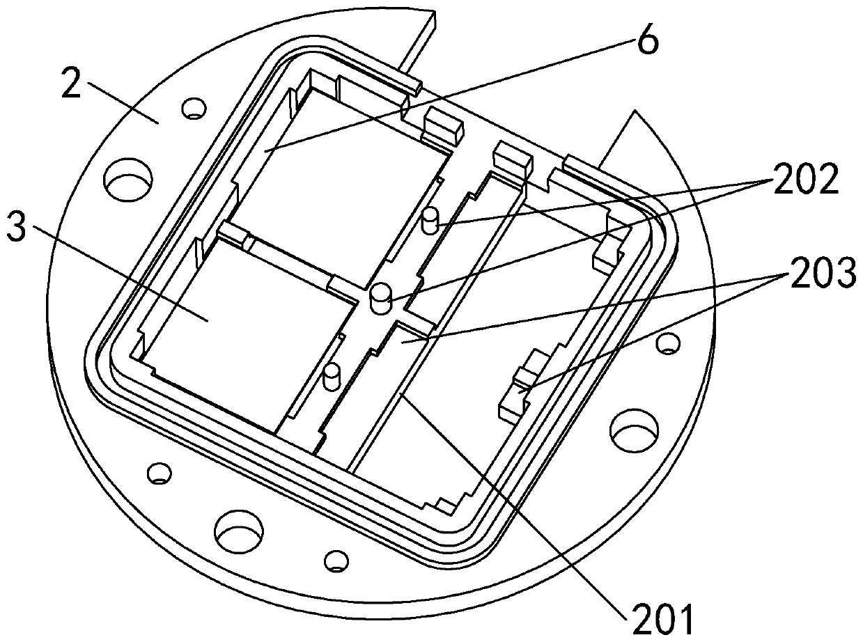
Ozone electrolysis chamber and ozone electrolysis chamber application module

An electrolysis chamber and ozone technology, applied in the field of ozone electrolysis chamber, can solve the problems of poor heat dissipation performance, burnout, PEM membrane electrode piece cannot dissipate heat, etc., and achieve the effect of increasing the concentration of ozone water, increasing the service life, and widening the use range

Pending Publication Date: 2020-06-09
GUANGZHOU DEPOSON ELECTRIC TECH
View PDF1 Cites 3 Cited by
  • Summary
  • Abstract
  • Description
  • Claims
  • Application Information

AI Technical Summary

Problems solved by technology

[0004] Chinese patent (application number 201710333784.3) discloses an ozone generator nozzle, which is provided with several mutually independent electrolytic chambers, and a positive electrolytic chamber is provided in the middle of each electrolytic chamber, and the two sides of the positive electrolytic chamber are respectively There is a negative electrode electrolysis chamber, and there are two cathodes, two PEM diaphragms, two diamond sheets and other components inside the electrolysis chamber, but because the electrodes are closely attached to the PEM diaphragm in this patent, it is difficult to make the ozone water produced by electrolysis flow, so the heat dissipation performance is poor, and the concentration of ozone water generated per unit area cannot be increased. The PEM film is also easy to burn out due to the inability of the electrode sheet to dissipate heat.
[0005] In the current application of electrolysis to prepare ozone water, the design of the chamber used for electrolysis fails to meet the production requirements, which greatly limits the use range of ozone. Therefore, it is of great significance to optimize the electrolysis structure.

Method used


Image

  • Ozone electrolysis chamber and ozone electrolysis chamber application module
  • Ozone electrolysis chamber and ozone electrolysis chamber application module
  • Ozone electrolysis chamber and ozone electrolysis chamber application module

Examples


Embodiment Construction

[0032] The following will clearly and completely describe the technical solutions in the embodiments of the present invention with reference to the accompanying drawings in the embodiments of the present invention. Obviously, the described embodiments are only part of the embodiments of the present invention, not all of them. Based on the embodiments of the present invention, all other embodiments obtained by persons of ordinary skill in the art without creative efforts fall within the protection scope of the present invention.

[0033] It should be noted that if there is a directional indication (such as up, down, left, right, front, back...) in the embodiment of the present invention, the directional indication is only used to explain the position in a certain posture (as shown in the accompanying drawing). If the specific posture changes, the directional indication will also change accordingly.

[0034] The invention provides an ozone electrolysis chamber.

[0035] refer t...


PUM


Abstract

The invention discloses an ozone electrolysis chamber, comprising a shell, wherein a water inlet and a water outlet are respectively formed in two ends of the shell; an inner cavity of the shell is anelectrolysis cavity; at least one electrode plate seat is arranged in the electrolysis cavity; at least one group of electrolysis assembly is arranged on the electrode plate seat; each electrolysis assembly comprises an anode plate, a proton exchange membrane and a cathode plate; a water passing seam is reserved between the electrolysis assembly and the inner wall of the electrode plate seat; first water passing holes are formed in the anode plate; second water passing holes are formed in the proton exchange membrane; an elastic component with the two ends abutting against the cathode plate and the inner wall of the shell respectively is arranged in the electrolysis cavity; and one side of the bottom of the electrode plate seat faces the water inlet. The ozone electrolysis chamber is goodin heat dissipation performance, the service life of the electrode plates is long, the concentration of generated ozone water is high, and incrustation accumulated on the surface of the electrode plates can be avoided. The invention further provides an ozone electrolysis chamber application module which can generate large-flow high-concentration ozone water in a short time and is extremely wide in application range.

Description

technical field [0001] The invention belongs to the technical field of ozone preparation, in particular to an ozone electrolysis chamber. Background technique [0002] Ozone is recognized as a broad-spectrum and efficient bactericide in the world. When ozone reaches a certain concentration, it can quickly kill bacteria in water and air. More importantly, ozone is reduced to oxygen after sterilization, so it is a A green and environmentally friendly disinfectant. Ozone is soluble in water and forms ozone water. In addition to killing bacteria in water, it can also decompose harmful pollutants such as organic matter in water, and at the same time have a certain decolorization effect on water. [0003] At present, in many countries and regions, ozone is widely used, such as in drinking water disinfection, medical water disinfection, sewage treatment, food factory and pharmaceutical factory air disinfection, paper bleaching and other industries and fields. At the same time, som...

Claims


Application Information

Patent Timeline
Patent Type & Authority Applications(China)
IPC IPC(8): C25B1/13C25B9/18C25B9/08C25B15/08C25B9/19
CPCC25B1/13C25B15/08C25B9/19C25B9/70C25B9/23C25B9/63C25B11/03C25B11/043C25B11/046C25B9/60C02F1/461C02F1/78C02F2201/782C02F2201/46115
Inventor 钟建华张文英潘裕富
Owner GUANGZHOU DEPOSON ELECTRIC TECH
Why Eureka
Try Eureka