Method for using high-pressure rotary jet grouting pile nozzle for road and bridge construction

A technology of high-pressure rotary grouting piles and nozzles, which is applied in the direction of drill bits, sheet pile walls, earthwork drilling and mining, etc. It can solve the problems of labor and time consumption, reduce construction efficiency, delay construction period, etc., and achieve the effect of improving stability

Active Publication Date: 2020-06-09
湖北晟弘建设工程有限公司
View PDF6 Cites 3 Cited by
  • Summary
  • Abstract
  • Description
  • Claims
  • Application Information

AI Technical Summary

Problems solved by technology

[0003] At present, the size of the pile hole formed by most of the existing drill bits is fixed, and it is impossible to flexibly adjust the size of the pile hole formed by the drill bit according to the actual use needs. On the outer wall, when the high-pressure rotary grouting pile machine is drilling in the soil, the gravel and soil in th...

Method used


Image

  • Method for using high-pressure rotary jet grouting pile nozzle for road and bridge construction
  • Method for using high-pressure rotary jet grouting pile nozzle for road and bridge construction
  • Method for using high-pressure rotary jet grouting pile nozzle for road and bridge construction

Examples


Embodiment 1

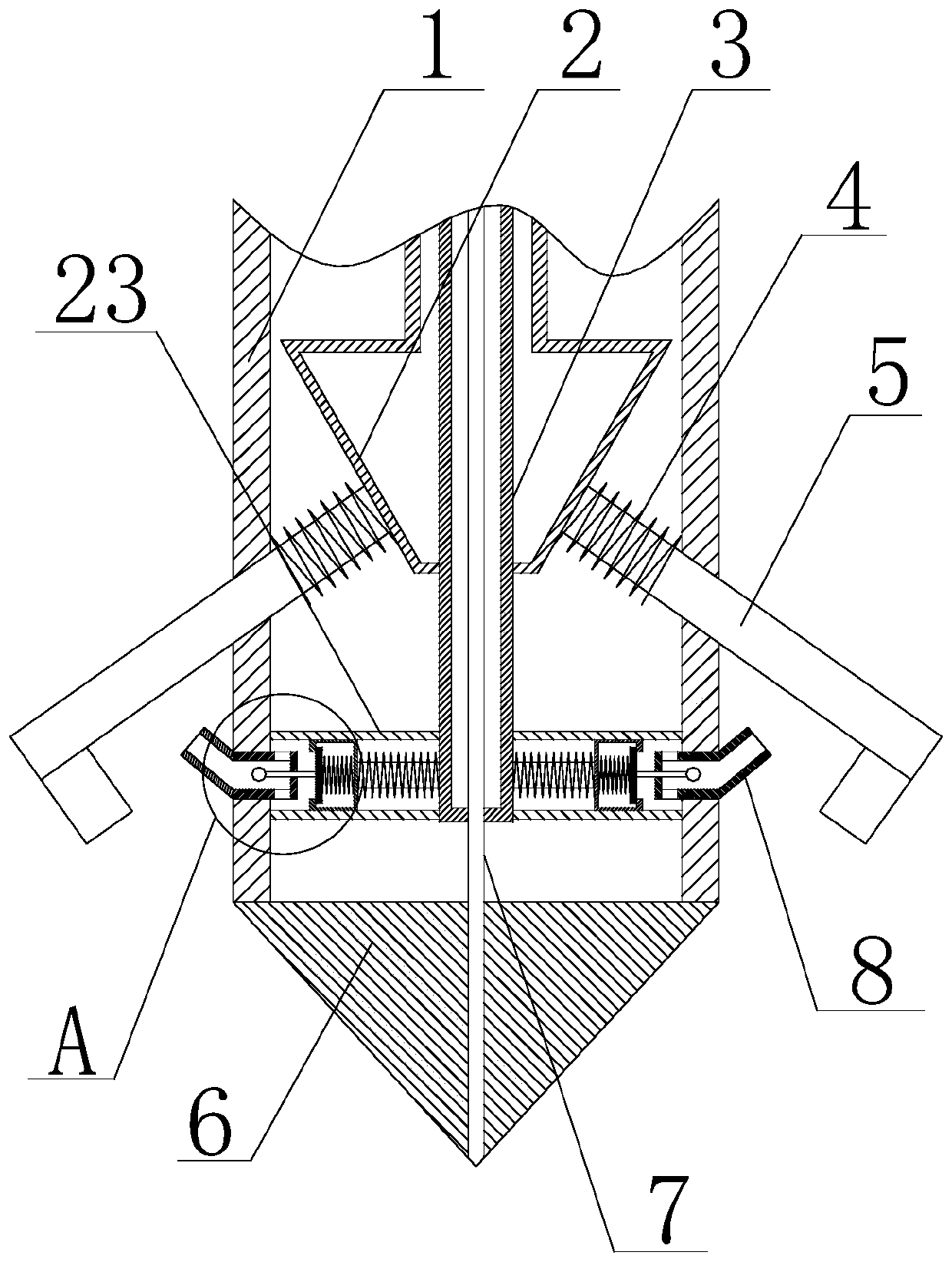
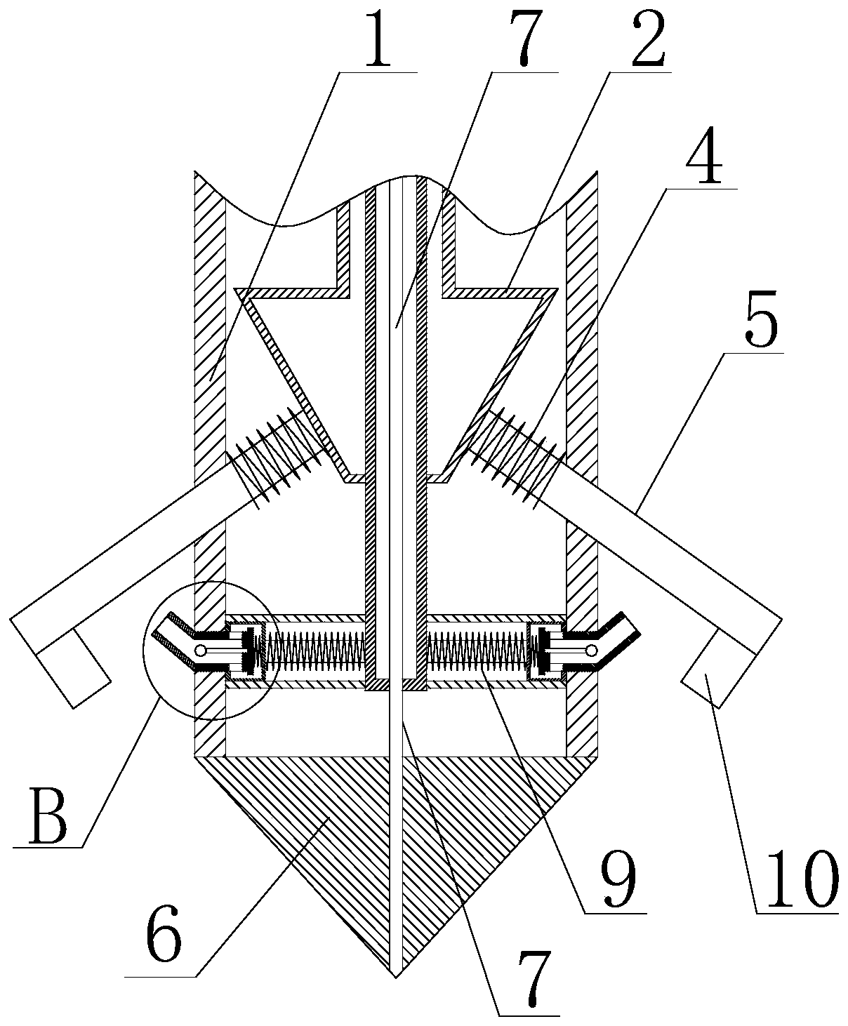
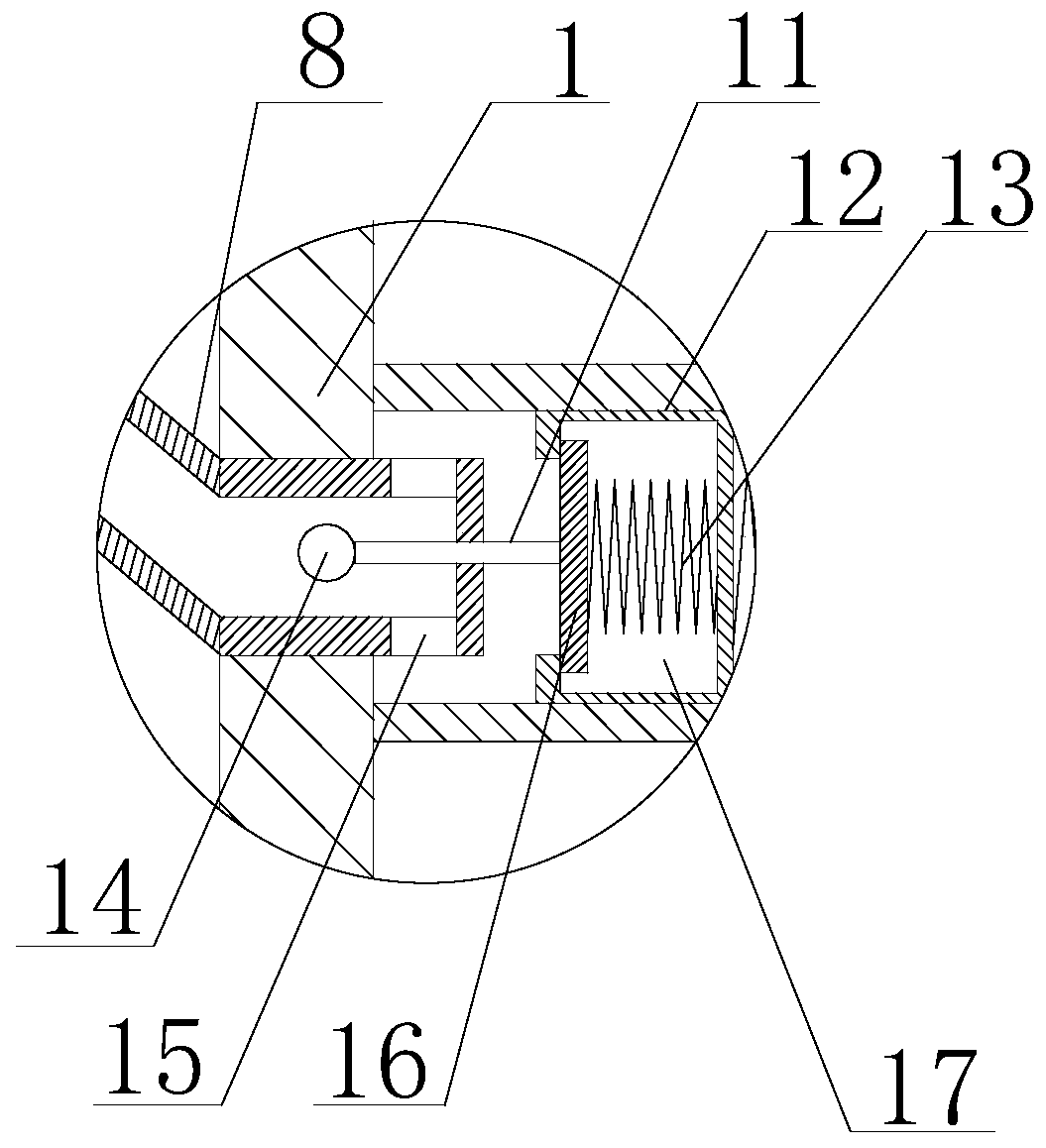
[0055] Such as Figure 1 to Figure 5 shown, including the following steps:

[0056] 1) Install the rod body 1 on the high-pressure rotary grouting pile machine;

[0057] 2) Use a water pump to feed high-pressure water into the liquid storage chamber 21 of the cone 22, and the high-pressure water pushes the movable assembly to move along the axial direction of the slurry delivery pipe 3, and pushes the drill blade 5 to extend out of the rod body 1;

[0058] 3) Adjust the protruding length of the drill blade 5 according to the inner diameter of the pile hole to be drilled;

[0059] 4) Use the high-pressure rotary grouting pile machine to drive the drill bit to rotate, and perform drilling operations on the soil;

[0060] 5) When the drill bit 6 is drilling down, when it is necessary to enlarge the inner diameter of the pile hole, continue to feed high-pressure water into the liquid storage chamber 21 of the cone 22, forcing the cone 22 to push the drill blade 5 to protrude out...

Embodiment 2

[0069] On the basis of Embodiment 1, the movable assembly 2 includes a conical member 22 and a connecting pipe 20, the conical member 22 is located at the bottom of the connecting pipe 20, and a liquid storage cavity 21 is arranged in the conical member 22, and the liquid storage The cavity 21 communicates with the connecting pipe 20, and the slurry delivery pipe 3 is inserted through the connecting pipe 20 and the liquid storage chamber 21 in sequence.

Embodiment 3

[0071] On the basis of Embodiment 1, the drill blade 5 is further provided with a first elastic member 4 , and the first elastic member 4 is sleeved on the drill blade 5 and located in the cavity of the rod body 1 .


PUM


Abstract

The invention discloses a method for using a high-pressure rotary jet grouting pile nozzle for road and bridge construction. The high-pressure rotary jet grouting pile nozzle comprises a rod body anda conical head, wherein the rod body is internally of a cavity structure, a grout conveying pipe is arranged in the cavity, a moving assembly is also arranged in the cavity of the rod body, the circumferential outer wall of the rod body is further provided with a plurality of drill blades, when the moving assembly moves towards the conical head, the moving assembly can push the drill blades to move in the direction away from the rod body, baffles are arranged on the side walls, facing the conical head, of the drill blades, stretchable pipes are further arranged in the cavity of the rod body, one ends of the stretchable pipes communicate with the grout conveying pipe, the other ends of the stretchable pipes are provided with joints, the circumferential outer wall of the rod body is furtherprovided with nozzle assemblies with the number same as the number of the drill blades, one ends of the nozzle assemblies face the drill blades, and the other ends of the nozzle assemblies are locatedin the cavity of the rod body. According to the method, the diameter of a pile hole drilled by the drill bit can be adjusted, then different use requirements can be met, meanwhile, it is guaranteed that in the drilling-down process of the drill bit, mud and stones in soil can be prevented from blocking the grout conveying pipe, and the construction efficiency is improved.

Description

technical field [0001] The invention relates to the technical field of road and bridge construction equipment, in particular to a method for using a high-pressure rotary jetting pile nozzle for road and bridge construction. Background technique [0002] High-pressure rotary grouting piles use high-pressure rotating nozzles to spray cement slurry into the soil layer and mix with the soil to form a continuous lapped cement reinforcement. The construction area is small, the vibration is small, the noise is low, and it has the advantages of saving wood and steel, durable, and low cost. It has been widely used in the basic engineering of hydraulic construction, industrial construction, civil construction and bridges. The high-pressure rotary grouting pile is to use a drilling rig to drill the rotary grouting pipe and the nozzle at the design elevation of the pile bottom, pass the pre-prepared grout through the high-pressure generating device to make the liquid flow obtain huge en...

Claims


Application Information

Patent Timeline
IPC IPC(8): E02D5/46E02D15/00E21B10/32
CPCE02D5/46E02D15/00E21B10/322
Inventor 李义政
Owner 湖北晟弘建设工程有限公司
Why Eureka
Try Eureka