Spring yield type energy dissipator for slope flexible protection system and design method
A technology of flexible protection and design method, applied in the direction of spring/shock absorber, excavation, instrument, etc., can solve the problems of insufficient energy dissipation capacity, inability to reuse, and inapplicability of energy consumers
- Summary
- Abstract
- Description
- Claims
- Application Information
AI Technical Summary
Problems solved by technology
Method used
Image
Examples
Embodiment 1
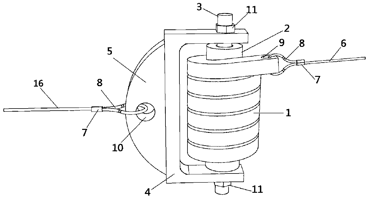
[0081] Such as Figure 1-2 As shown, a spring yield type energy dissipator used for slope flexible protection system, the energy dissipator consists of a spring steel (1), a rotating shaft (2), a pin shaft (3 ), a C-shaped clamp (4) and a curved lug (5). The spring steel (1) is mechanically rolled from square steel around the rotating shaft (2), one end of the spring steel (1) is welded on the rotating shaft (2), and the other end is tightly wound around the rotating shaft (2) for several turns before it rotates The shaft (2) protrudes tangentially for a certain length, and the protruding end is provided with a first connection hole (9) connected to the first support rope (6) of the flexible protection system;
[0082] The rotating shaft (2) has a built-in pin shaft (3) and can rotate around the pin shaft (3). The two ends of the pin shaft (3) are connected to the C-shaped clamp (4) through bolts (11). The ear plate (5) is welded and fixed, and the arc-shaped ear plate (5) i...
Embodiment 2
[0105] Such as image 3 As shown, a combination and design method of a spring yield type energy dissipator for a slope flexible protection system, the energy dissipator includes 3 spring steels (1), 3 rotating shafts (2) when used in combination according to this embodiment ), 3 pin shafts (3), 1 C-shaped clamp (4) and 1 arc ear plate (5).
[0106] Such as image 3 As shown, when using the energy dissipator in combination according to this embodiment, three main structures of the energy dissipator when used alone are formed according to the method in embodiment 1, and arranged in a certain way to form the energy dissipator when used in combination according to this embodiment. The main structure of the energy device.
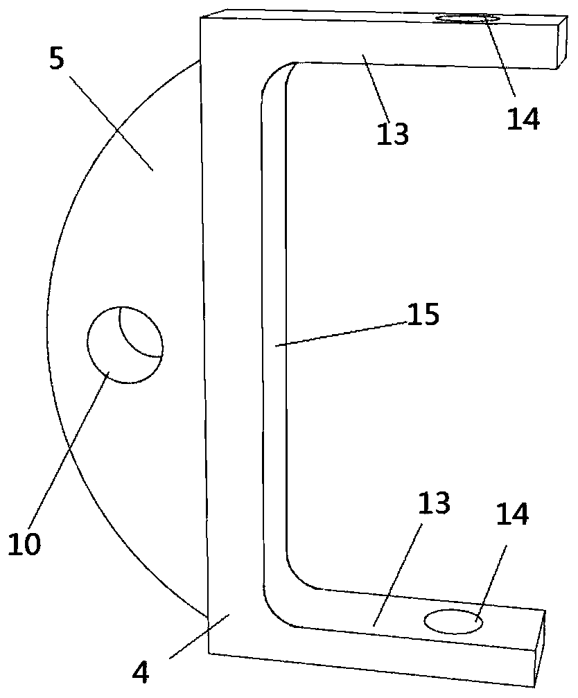
[0107] When using this energy dissipator in combination according to this embodiment, the clamp flange plate (13) of the C-shaped clamp (4) in Embodiment 1 is replaced with a triangle, and each clamp flange plate (13) reserves 3 clamp connections holes (14), ...
PUM
| Property | Measurement | Unit |
|---|---|---|
| Tensile length | aaaaa | aaaaa |
Abstract
Description
Claims
Application Information
 - R&D
- Intellectual Property
- Life Sciences
- Materials
- Tech Scout
- Unparalleled Data Quality
- Higher Quality Content
- 60% Fewer Hallucinations
Browse by: Latest US Patents, China's latest patents, Technical Efficacy Thesaurus, Application Domain, Technology Topic, Popular Technical Reports.
© 2025 PatSnap. All rights reserved.Legal|Privacy policy|Modern Slavery Act Transparency Statement|Sitemap|About US| Contact US: help@patsnap.com


