Screw joint spherical hinge structure suitable for truss connection

A screw connection and spherical hinge technology, applied in building structure, construction, etc., can solve problems such as very high requirements for construction plans, waste of material resources, affecting service life, etc., to meet the requirements of multi-truss connection, reduce work difficulty, and improve The effect of assembly efficiency

Pending Publication Date: 2020-06-09
NANCHANG UNIV
View PDF0 Cites 2 Cited by
  • Summary
  • Abstract
  • Description
  • Claims
  • Application Information

AI Technical Summary

Problems solved by technology

The skeleton structure of the expressway toll station is constructed by welding trusses to trusses. This welding method is not only time-consuming but also laborious, which is not conducive to the assembly efficiency of the trusses.
Moreover, under the action of high temperature, a heat-affected zone will be formed near the weld of the truss, and the mechanical properties of the steel will change, which will make the material brittle and affect the service life
Once the shed needs to be dismantled due to long-term aging, since the truss cannot be disassembled after welding, workers can only dismantle it by cutting the truss. However, the welded structure has continuity, and once a local crack occurs, it is easy to expand to the whole. The construction plan for cutting and demolition is very demanding
Once the cutting is not done properly, it is easy to cause the local area or even the whole greenhouse to collapse
Moreover, this cutting method is also likely to cause waste of material resources

Method used


Image

  • Screw joint spherical hinge structure suitable for truss connection
  • Screw joint spherical hinge structure suitable for truss connection
  • Screw joint spherical hinge structure suitable for truss connection

Examples


Embodiment Construction

[0019] In order to make the purpose, technical means and effects of the present invention more understandable, the present invention will be described in detail below in conjunction with the accompanying drawings and specific embodiments. It should be understood that the specific embodiments described this time are only for explaining the present invention. Based on the embodiments of the present invention, all other embodiments obtained by persons of ordinary skill in the art without making creative efforts belong to the protection scope of the present invention.

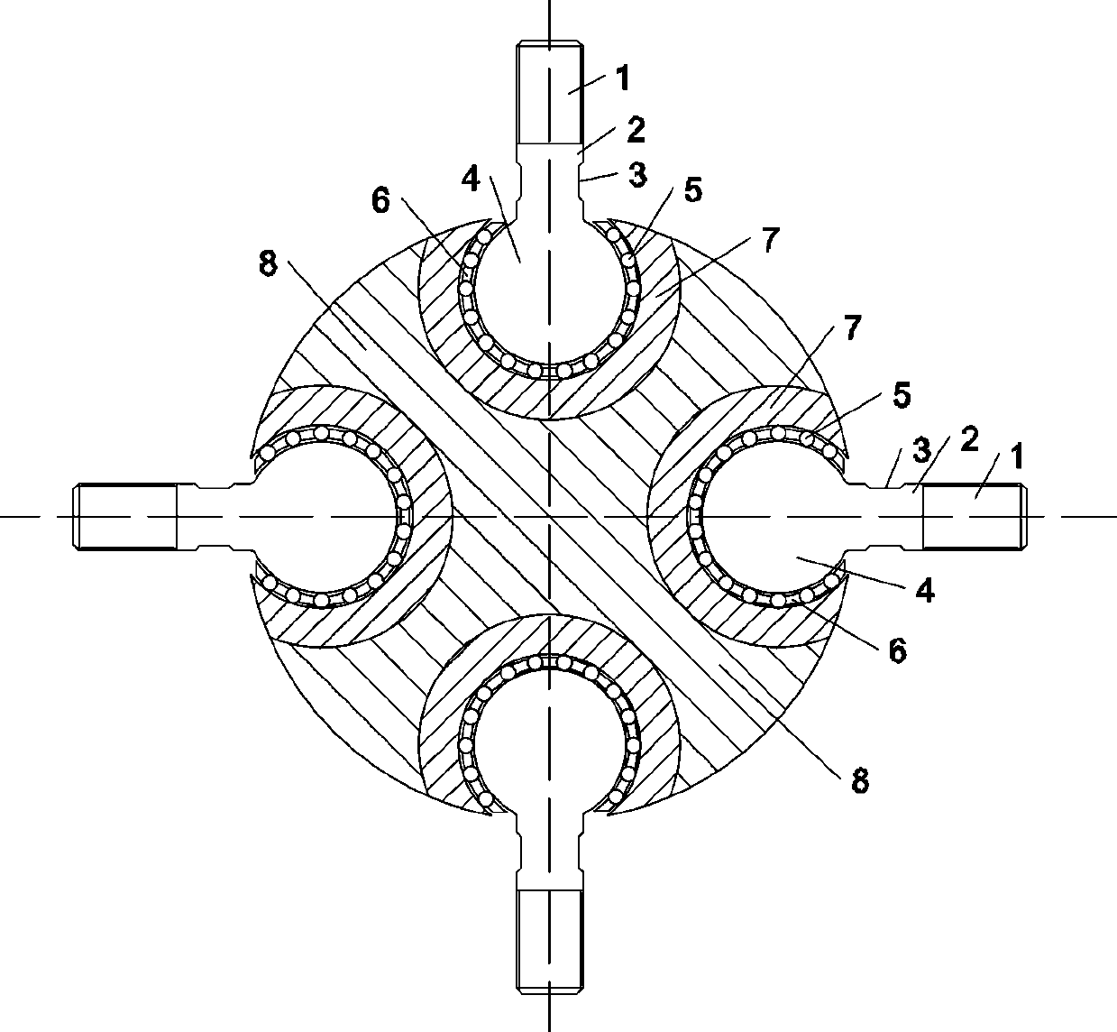
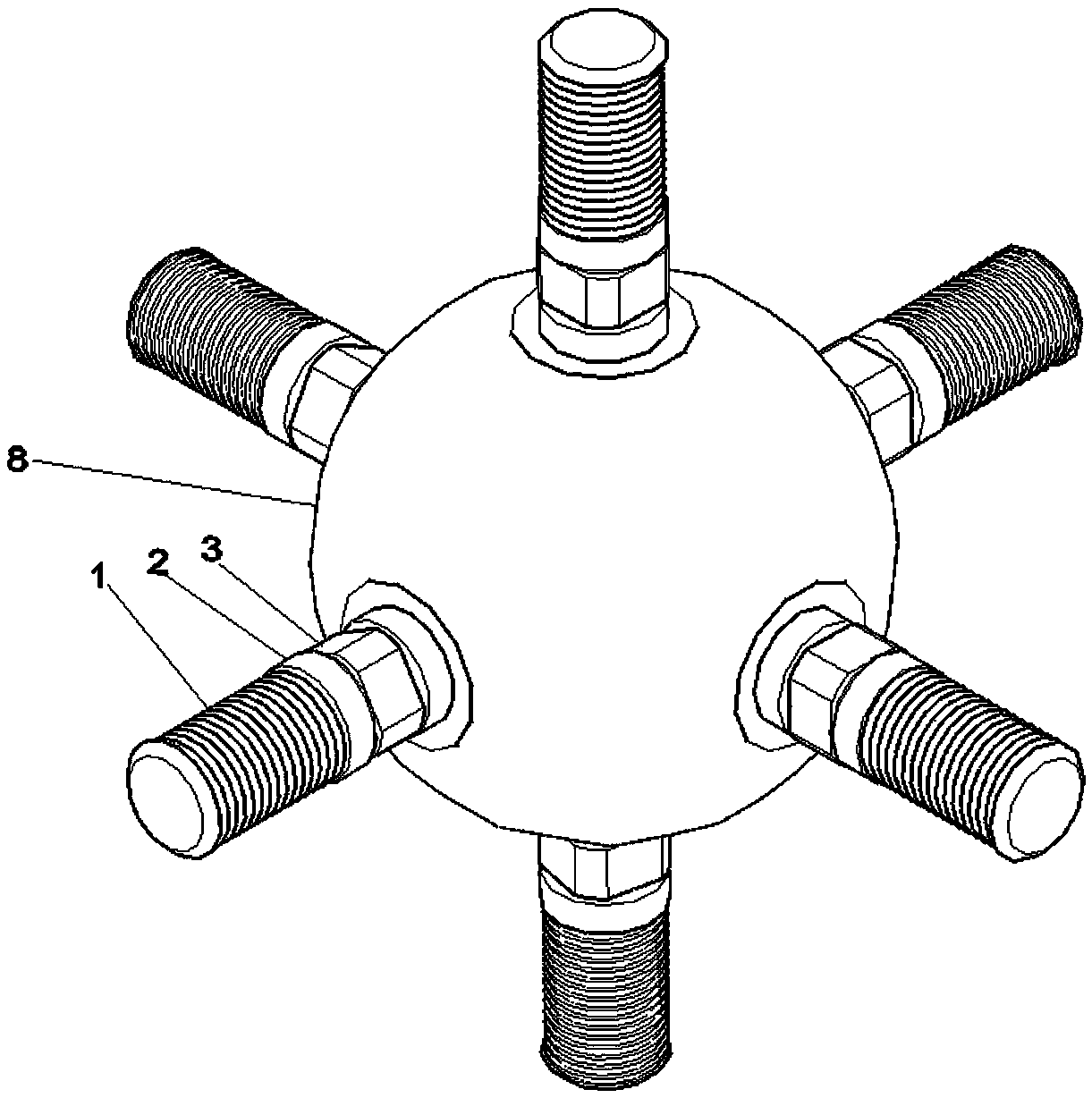
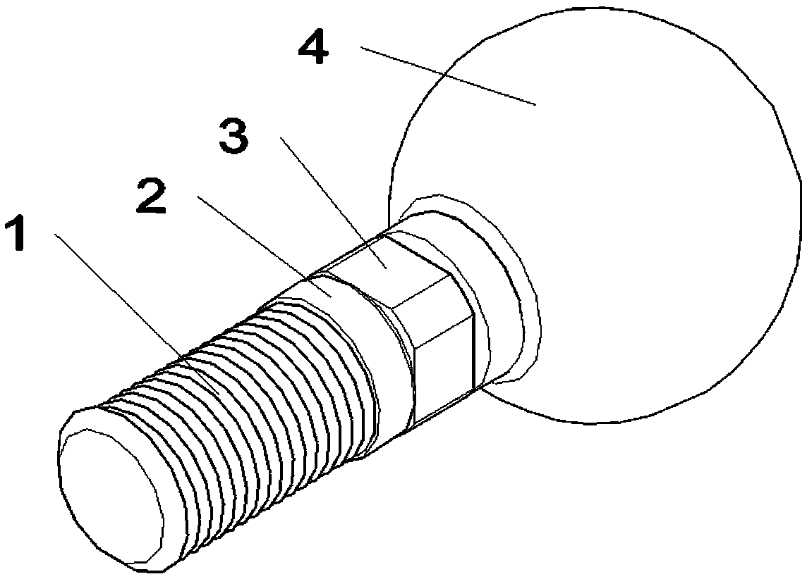
[0020] Such as Figure 1-Figure 3 As shown, the present invention is a screwed ball joint structure suitable for truss connection, including a metal ball seat 8, a raceway 7, a ball pin sleeve with holes 6, a ball 5, a ball head 4, and a rod integrally formed with the ball head 4 2. The metal ball seat 8 has a spherical structure, and its surface is provided with at least one hollow cavity for placing the raceway ...


PUM


Abstract

The invention discloses a screw joint spherical hinge structure suitable for truss connection. The screw joint spherical hinge structure suitable for truss connection comprises a metal ball seat, a raceway, a ball pin sleeve with a hole, balls, a ball head and a rod body integrally formed with the ball head; the metal ball seat is of a spherical structure, the surface of the metal ball seat is provided with at least one hollow inner cavity for placing the raceway, the raceway forms the hollow inner cavity, one side of the raceway is provided with an opening for the rod body to penetrate through, the ball pin sleeve with the hole is fixedly installed in an inner cavity of the raceway, the ball pin sleeve with the hole is provided with a plurality of installation holes for installing the balls, the ball head is movably installed in the inner cavity of the ball pin sleeve with the hole and slides in cooperation with the balls, and external threads are arranged on the outer wall of the free end of the rod body. According to the screw joint spherical hinge structure suitable for truss connection, the external thread at the free end of the rod body is used for being in threaded connection with the truss with the internal thread, an original welding connection mode is replaced, the additionally-arranged working difficulty caused by the adoption of the welding connection mode is lowered, the assembling time is shortened, and the assembling efficiency is improved.

Description

technical field [0001] The invention relates to the field of spherical joint structure design, in particular to a screwed spherical joint structure suitable for truss connection. Background technique [0002] my country's expressway network has developed rapidly in recent years, extending in all directions in the middle of the country. The total scale of my country's expressway network is about 85,000 kilometers, which is the largest expressway system in the world, and many expressway toll stations, also known as "toll sheds", will be built accordingly. The skeleton structure of the expressway toll station is constructed by welding trusses to trusses. This welding method is not only time-consuming but also laborious, which is not conducive to the assembly efficiency of the trusses. Moreover, under the action of high temperature, a heat-affected zone will be formed near the weld of the truss, and the mechanical properties of the steel will change, which will make the materia...

Claims


Application Information

Patent Timeline
Patent Type & Authority Applications(China)
IPC IPC(8): E04B1/19E04B1/343E04B1/58
CPCE04B1/1906E04B1/34326E04B2001/196E04B2001/1969
Inventor 田钦李顺治童治豪廖金莲
Owner NANCHANG UNIV
Why Eureka
Try Eureka