Plug connector combination

A plug connector and connection area technology, which is applied in the field of plug connector combinations that can save space around equipment interfaces, can solve problems such as occupied space, poor contact, and cables are easily bent and damaged, so as to save space and improve plugging capabilities. The effect of connecting stability and reducing the probability of cable bending

Pending Publication Date: 2020-06-09
南京奥利弗科技发展有限公司
View PDF0 Cites 0 Cited by
  • Summary
  • Abstract
  • Description
  • Claims
  • Application Information

AI Technical Summary

Problems solved by technology

[0002] In the existing cable plug connector design, the plug connector is generally soldered to the plane where the circuit board is located in parallel, and then the cable is soldered to the rear end of the plug connector, and the insertion direction of the wiper connector is in line with the circuit board. The planes where they are located are parallel to each other, and the extension direction of the cable is parallel to the insertion direction of the plug connector. However, when the cable plug connector is plugged into the device interface, on the one hand, the plug connector and the circuit board structure occupy On the other hand, the cable is easily bent and damaged, resulting in poor contact

Method used


Image

  • Plug connector combination
  • Plug connector combination
  • Plug connector combination

Examples


Embodiment Construction

[0021] The present invention will be described in detail below with reference to the embodiments shown in the accompanying drawings. However, this embodiment does not limit the present invention, and any structural, method, or functional changes made by those skilled in the art according to this embodiment are included in the protection scope of the present invention.

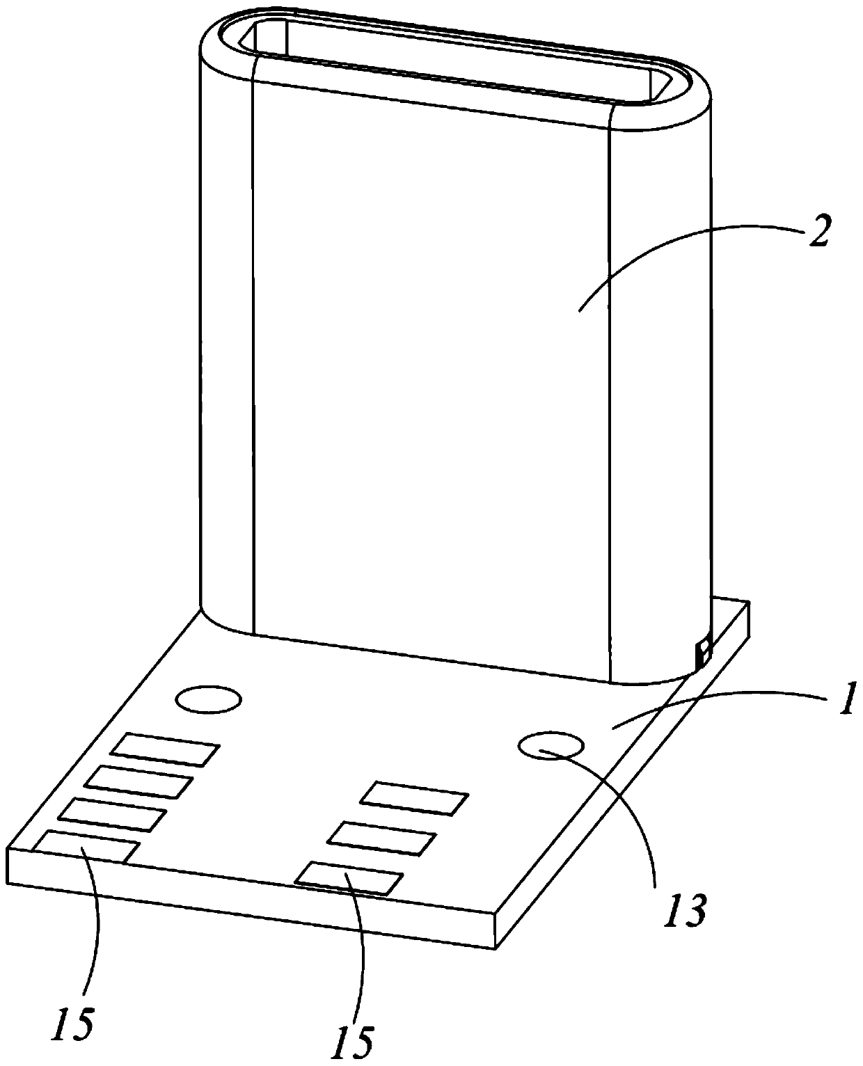
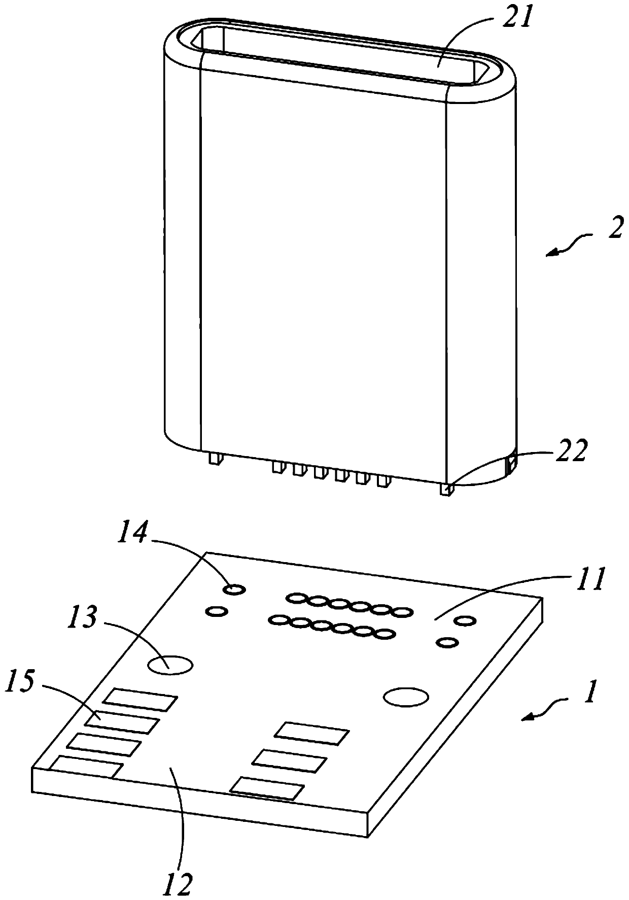
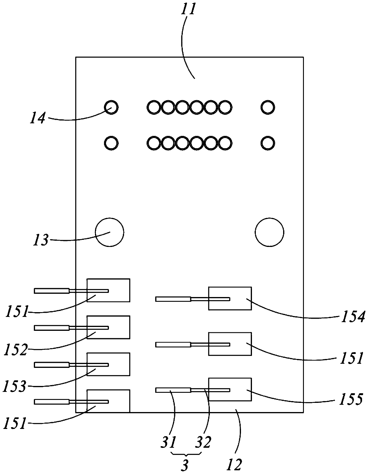
[0022] Please refer to Figure 1 to Figure 5 Shown is the plug connector combination of the present invention, which is used to work in electrical connection with a socket connector (not shown). The plug connector assembly includes a circuit board 1, a plug connector 2 that is welded on the circuit board 1 and can be plugged with a pair of connectors in front and back, wherein the insertion direction of the plug connector 2 is the same as The plane where the circuit board 1 is located is perpendicular to, and the circuit board 1 is provided with a first connection area 11 for connecting the plug connector 2 an...


PUM


Abstract

The invention provides a plug connector combination, which comprises a circuit board and a plug connector which is welded on the circuit board and can be positively and negatively plugged with a butting connector, wherein the plugging direction of the plug connector is perpendicular to the plane where the circuit board is located, and the circuit board is provided with a first connecting area usedfor being connected with the plug connector and a second connecting area used for being connected with an external cable. According to the plug connector combination, the space near an equipment interface is saved, and the cable bending probability is reduced, so that the plugging stability is improved.

Description

technical field [0001] The invention relates to a plug connector combination, in particular to a plug connector combination which can save space around equipment interfaces. Background technique [0002] In the existing cable plug connector design, the plug connector is generally soldered to the plane where the circuit board is located in parallel, and then the cable is soldered to the rear end of the plug connector, and the insertion direction of the wiper connector is in line with the circuit board. The planes where they are located are parallel to each other, and the extension direction of the cable is parallel to the insertion direction of the plug connector. However, when the cable plug connector is plugged into the device interface, on the one hand, the plug connector and the circuit board structure occupy On the other hand, the cable is easily bent and damaged, resulting in poor contact. [0003] In view of this, it is necessary to improve the existing plug connector...

Claims


Application Information

Patent Timeline
Patent Type & Authority Applications(China)
IPC IPC(8): H01R12/55H01R12/71H01R13/502H01R13/627H01R13/629H01R13/66
CPCH01R12/55H01R12/71H01R13/502H01R13/627H01R13/629H01R13/66
Inventor 乔峰
Owner 南京奥利弗科技发展有限公司
Why Eureka
Try Eureka