
Speed reduction and motor installation supporting device of speed reduction motor

A technology of geared motor and support device, applied in electromechanical devices, electrical components, electric components, etc., can solve problems such as poor versatility, large space occupation, power reduction, etc., to save material costs, prolong service life, and reduce motor costs. The effect of consumables

Inactive Publication Date: 2020-06-09
BEIJING JINGCHUANGDA SCI & TECH
View PDF0 Cites 0 Cited by
  • Summary
  • Abstract
  • Description
  • Claims
  • Application Information

AI Technical Summary

Problems solved by technology

When the load torque of the pulley is too large or after a period of use, the gear shaft core is prone to inclination due to insufficient strength, causing transmission failure or slipping, and has the disadvantages of large volume, large space occupation, and high cost.
The other is that the first-stage pulley is installed on the rear bracket, and the second-stage pulley is installed on the front bracket, which takes up a lot of space. It is difficult to design the air duct when the motor is matched with the electrical enclosure, resulting in poor heat dissipation and reduced power due to no air duct.
The deceleration support devices of these two motors can only be used for one type, and the versatility is very poor

Method used


Image

  • Speed reduction and motor installation supporting device of speed reduction motor
  • Speed reduction and motor installation supporting device of speed reduction motor
  • Speed reduction and motor installation supporting device of speed reduction motor

Examples


Embodiment Construction

[0015] The present invention will be described in further detail below in conjunction with the embodiments in the accompanying drawings, but this does not constitute any limitation to the present invention.

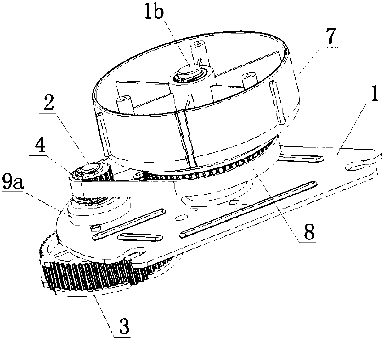
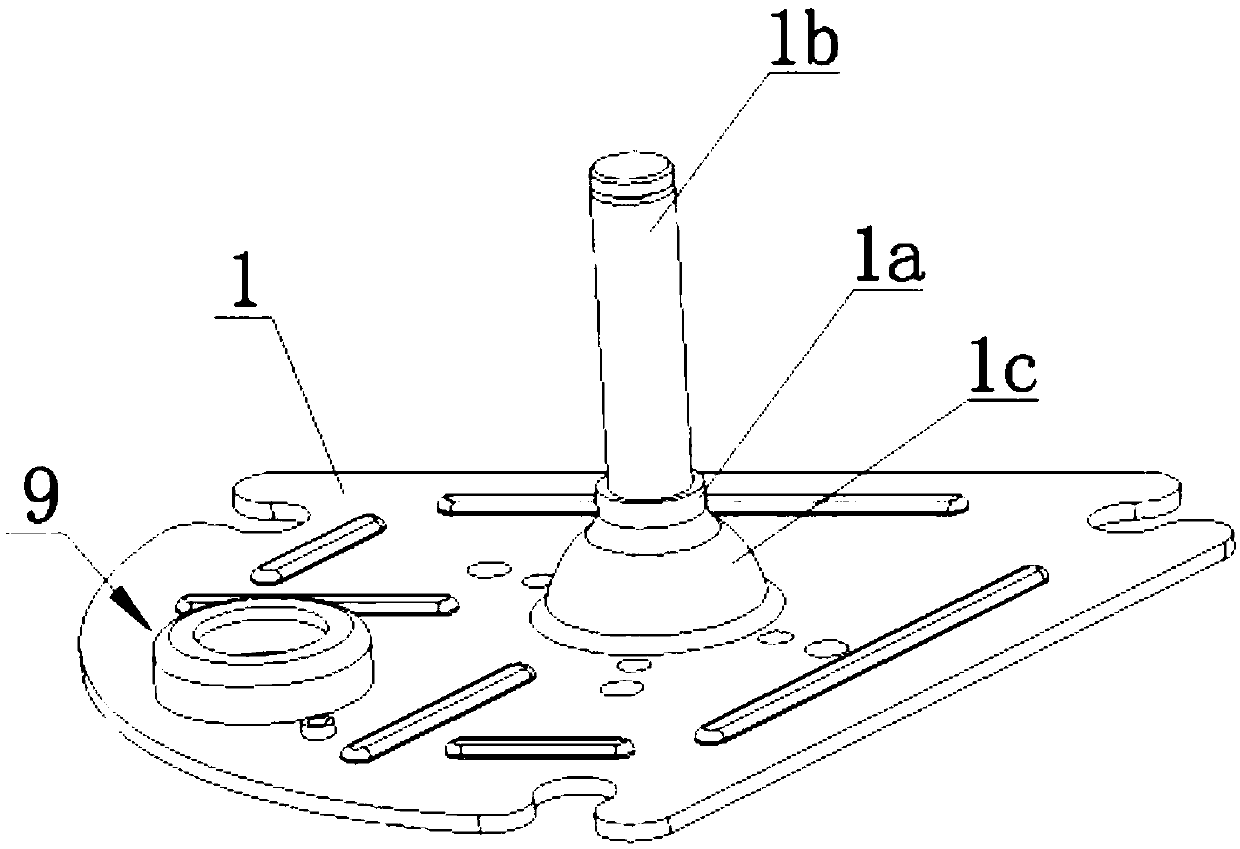
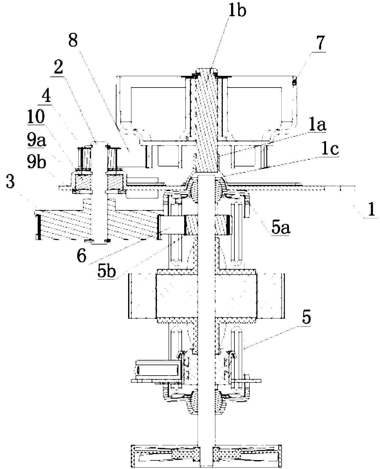
[0016] refer to Figure 1 to Figure 3 As shown, the deceleration and motor installation support device of a geared motor of the present invention comprises a motor mounting plate 1, a gear shaft 2 is arranged on the motor mounting plate 1, a bearing chamber 9 is arranged on the motor mounting plate 1, and a bearing chamber 9 is arranged on the bearing A bearing 10 is provided in the chamber 9, and the gear shaft 2 is fixed on the motor mounting plate 1 through the bearing 10; the bearing chamber 9 in this embodiment is composed of a bearing seat 9a and a fixed pressure plate 9b arranged at the opening of the bearing seat 9a ; The overall structure of the bearing seat 9a and the motor mounting plate 1 integrally formed. The two ends of the gear shaft 2 are respectively co...


PUM


Abstract

The invention discloses a speed reduction and motor installation supporting device of a speed reduction motor, which belongs to the technical field of speed reduction motor. The device is technicallycharacterized by comprising a motor installation plate, a gear shaft is arranged on the motor installation plate, the two ends of the gear shaft are connected with a first-stage gear and a second-stage gear respectively, a motor is mounted on the motor installation plate on the side edge of the first-stage gear, and a rotor gear on a rotating shaft of the motor is in linkage with the first-stage gear through a first-stage belt; an output wheel is arranged on the motor installation plate on the side edge of the second-stage gear, and is linked with the second-stage gear through a second-stage belt. The invention aims to provide the speed reduction and motor installation support of the speed reduction motor, which is reasonable in structure, high in efficiency and good in universality; and the device is used for installing and decelerating the speed reduction motor.

Description

technical field [0001] The present invention relates to a support device, more specifically, to a deceleration and motor installation support device for a deceleration motor. Background technique [0002] At present, reduction motors with pulleys are widely used in household appliances such as juicers and meat blenders. One is that the pulleys are installed on the front bracket of the motor, which requires high verticality, strength and manufacturing accuracy of the gear shaft cores on the primary and secondary pulleys. . When the load torque of the pulley is too large or after a period of use, the gear shaft core is prone to inclination due to insufficient strength, causing transmission failure or slipping, and has the disadvantages of large volume, large space occupation, and high cost. The other is that the first-stage pulley is installed on the rear bracket, and the second-stage pulley is installed on the front bracket, which takes up a lot of space. It is difficult to ...

Claims


Application Information

Patent Timeline
Patent Type & Authority Applications(China)
IPC IPC(8): H02K7/10H02K7/116
CPCH02K7/1016H02K7/116
Inventor 刘丹
Owner BEIJING JINGCHUANGDA SCI & TECH
Learn More