A cutting machine tool for metal processing

A cutting machine tool and metal processing technology, which is applied to metal processing machinery parts, metal processing equipment, manufacturing tools, etc., can solve the problems of cutting fluid splashing, increasing, and cutting fluid polluting the working environment, so as to prevent pollution of the working environment Effect

Active Publication Date: 2021-03-16
CHANGDE CITY ZHONGKAI MACHINERY IND
View PDF5 Cites 0 Cited by
  • Summary
  • Abstract
  • Description
  • Claims
  • Application Information

AI Technical Summary

Problems solved by technology

[0005] Aiming at the deficiencies in the prior art, the purpose of the present invention is to provide a cutting machine tool for metal processing to solve the problem of increasing the speed of the tool in the prior art due to the higher the tool speed, the temperature generated by its contact with the metal will rise faster. At the same time, it is also necessary to increase the water outlet speed of the cutting fluid to quickly cool down, and the cutting fluid directly flushing on the workbench will cause the cutting fluid to splash, and it will increase with the increase of the flow rate, which will affect the cutting. While the fluid is being recycled, the splashing of the cutting fluid will pollute the working environment

Method used


Image

  • A cutting machine tool for metal processing
  • A cutting machine tool for metal processing
  • A cutting machine tool for metal processing

Examples


Embodiment 1

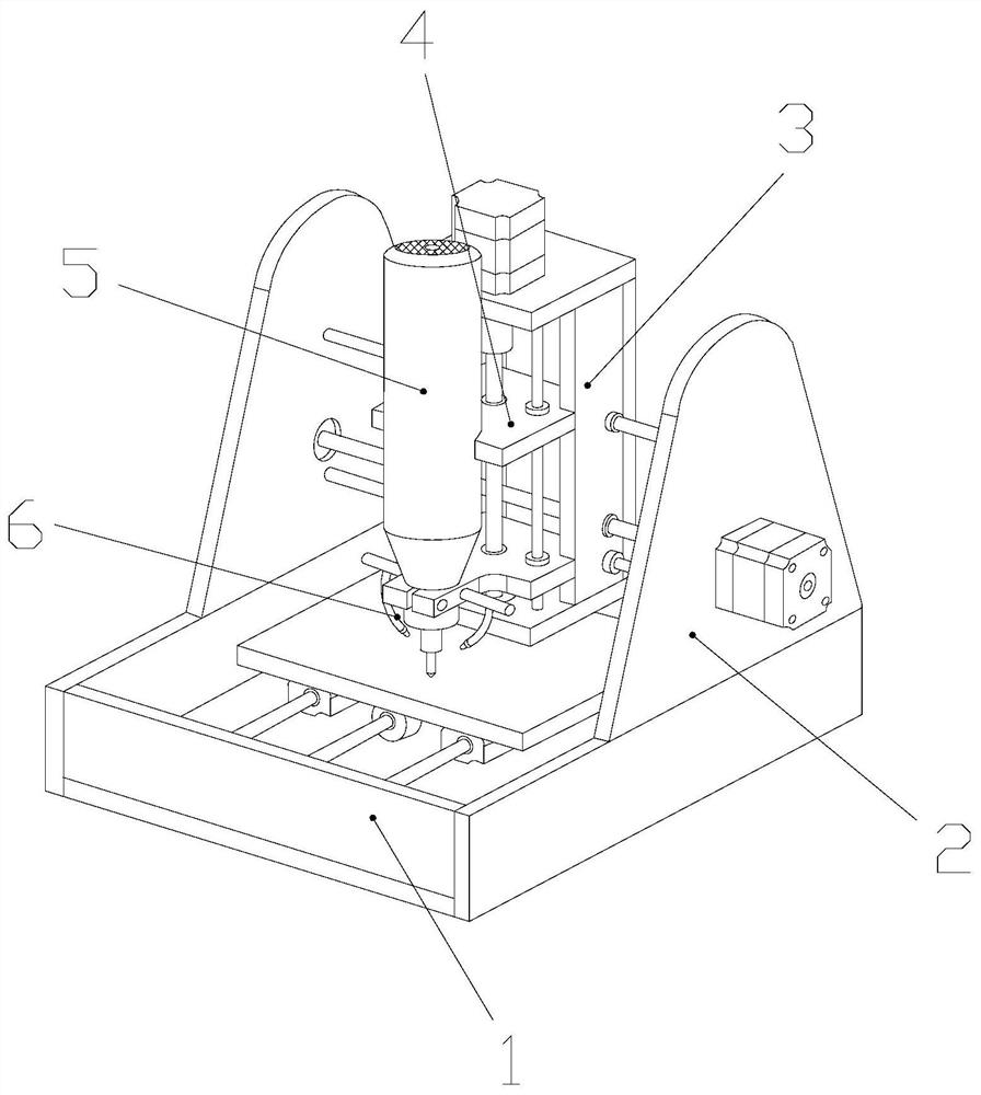
[0027] Example 1: Please refer to Figure 1-Figure 5 , the specific embodiments of the present invention are as follows:

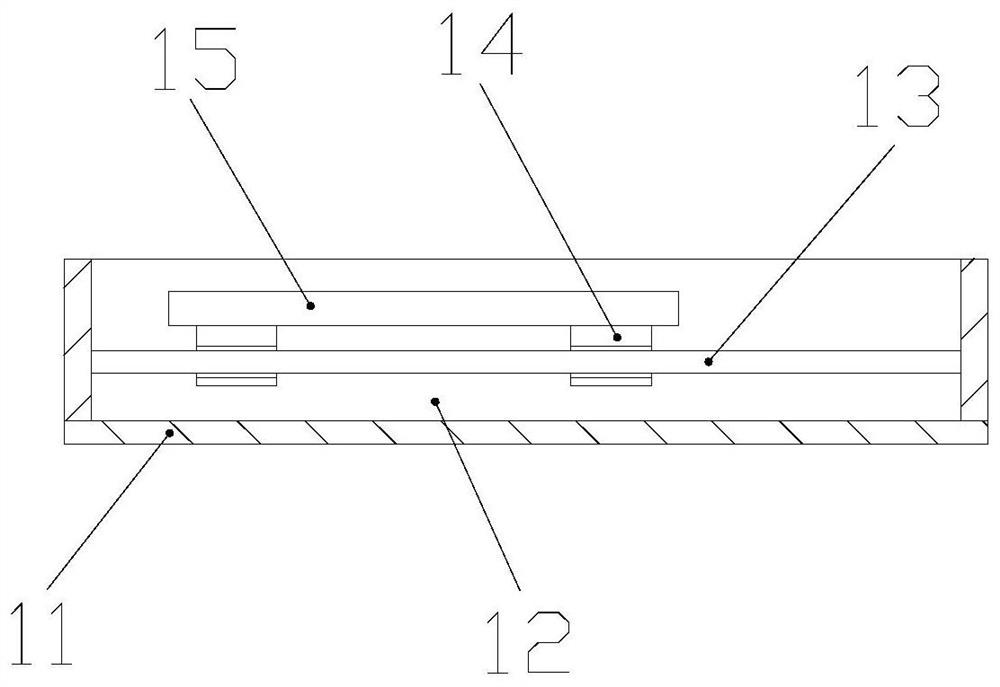
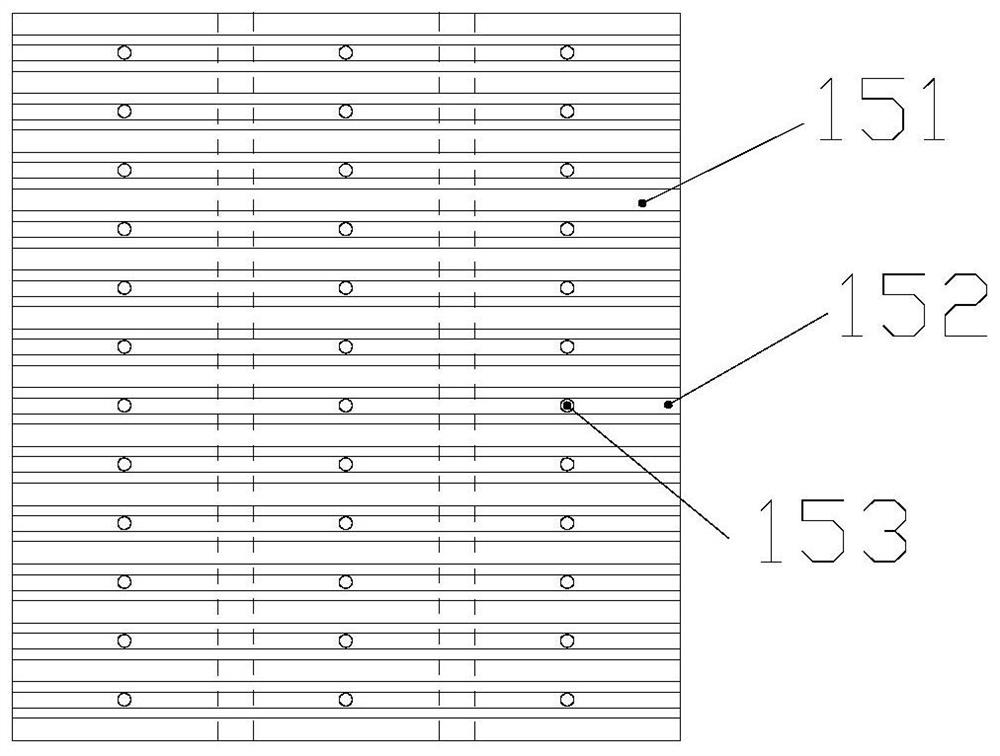
[0028] Its structure includes a working base 1, a side frame 2, a lateral moving frame 3, a longitudinal moving frame 4, a cutting head 5, and a cooling pipe 6. The side frame 2 is vertically installed on the side of the working base 1 and welded together. The lateral moving frame 3 is installed between the side frames 2 and is movably connected, the longitudinal moving frame 4 is embedded in the lateral moving frame 3 and is movably connected, the cutting head 5 is vertically installed on the front end of the longitudinal moving frame 4 and is mechanically connected, The cooling pipe 6 is located on both sides of the cutting head 5; the working base 1 includes an outer box body 11, a storage chamber 12, a guide rail 13, a slider 14, and a workbench 15, and the storage chamber 12 is arranged on the outer box body 11 The inner side is an integrated structu...

Embodiment 2

[0035] Example 2: Please refer to Figure 5-Figure 7 , the specific embodiments of the present invention are as follows:

[0036] The diversion structure 52c includes a sloping plate c1, a diversion cavity c2, a connecting plate c3, a movable rod c4, and a top c5. The diversion cavity c2 is provided on the outside of the sloping plate c1 and is an integrated structure. The connecting plate c3 Vertically installed on the lower end of the inclined plate c1 and welded together, the movable rod c4 is installed on the inner side of the connecting plate c3 and adopts a flexible connection, and the upward end of the inclined plate c1 converges to form the apex c5.

[0037] refer to Figure 5 , the inner side of the connecting plate c3 is provided with a slot hole and extends obliquely parallel to the sloping plate c1, the upper end of the movable rod c4 is slidably connected with the slot hole, and the connecting plate c3 at the lower end of the sloping plate c1 can be moved accordi...


PUM


Abstract

The invention discloses a cutting machine tool for metal processing. The structure includes a working base, a side frame, a lateral moving frame, a longitudinal moving frame, a cutting head, and a cooling pipe. The side frame is vertically installed on the side of the working base, and the lateral moving frame is installed on the side. Between the frames, the longitudinal moving frame is embedded inside the horizontal moving frame, the cutting head is vertically installed on the front end of the longitudinal moving frame, the cooling pipe is arranged on both sides of the cutting head, the working base includes the outer box, the storage cavity, the guide rail, the slider, the working The storage chamber is set on the inner side of the outer box, the guide rail is installed horizontally on the inner side of the outer box, the slider is sleeved on the outer side of the guide rail, and the working table is fixed on the upper end of the slider horizontally. The rebound position of the cutting fluid is limited to prevent it from splashing outwards and ensure the processing environment; a diversion structure is set on the inside of the side plate to better recycle the cutting fluid while preventing the cutting fluid from splashing out. Prevent it from polluting the working environment.

Description

technical field [0001] The invention belongs to the field of machine tools, and in particular relates to a cutting machine tool for metal processing. Background technique [0002] Metal cutting is mainly the technical cutting of metal materials, using tools to process metal materials to form the required shape, and cutting machine tools include vertical lathes and horizontal lathes, in which flat metal materials are cut At the same time, a vertical lathe is usually used for processing. Due to the contact cutting between the metal material and the cutting tool, a higher temperature will be generated. In order to prevent deformation, it is necessary to use cutting fluid to cool the part being processed to ensure the normal processing of the metal. But now There are the following deficiencies in the technology: [0003] Due to the higher the tool speed, the temperature generated by the contact with the metal will rise faster, so that when the tool speed is increased, the water...

Claims


Application Information

Patent Timeline
Patent Type & Authority Patents(China)
IPC IPC(8): B23Q11/08B23Q11/10
CPCB23Q11/08B23Q11/10
Inventor 王坤
Owner CHANGDE CITY ZHONGKAI MACHINERY IND
Why Eureka
Try Eureka