A kind of intelligent cargo trolley for construction site
A technology for construction site and cargo, applied in the direction of vehicles, motor vehicles, transport objects, etc. for freight transportation, it can solve the problems of casualties, time-consuming and labor-intensive, complicated and complicated operations, etc., and achieves a high degree of automation and intelligence. Simple and reasonable structure, stable and fast transfer effect
- Summary
- Abstract
- Description
- Claims
- Application Information
AI Technical Summary
Problems solved by technology
Method used
Image


Examples
Embodiment 1
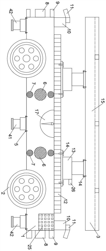
[0023] see Figure 1~3 , an intelligent loading trolley for a construction site, comprising: a base 1, a running device 2, a loading platform 3, a balancer 17 and a control box 25, the running device 2 is rollingly arranged on the base 1, and the bottom of the base 1 A support hydraulic push rod 41 and an adjustment hydraulic push rod 42 are provided, and the support hydraulic push rod 41 and the adjustment hydraulic push rod 42 are fixedly arranged on the base 1 through bolts 5, and the bottom of the support hydraulic push rod 41 and the adjustment hydraulic push rod 42 are arranged There are anti-compression friction pads, the thickness of the anti-compression friction pads is 15mm, the adjustment hydraulic push rod 42 is symmetrically arranged on both sides of the supporting hydraulic push rod 41, and the front and rear connectors 8 and front and rear shock-absorbing columns 9 are symmetrically arranged on the front and rear sides of the base 1, Both sides of the side wall ...
Embodiment 2
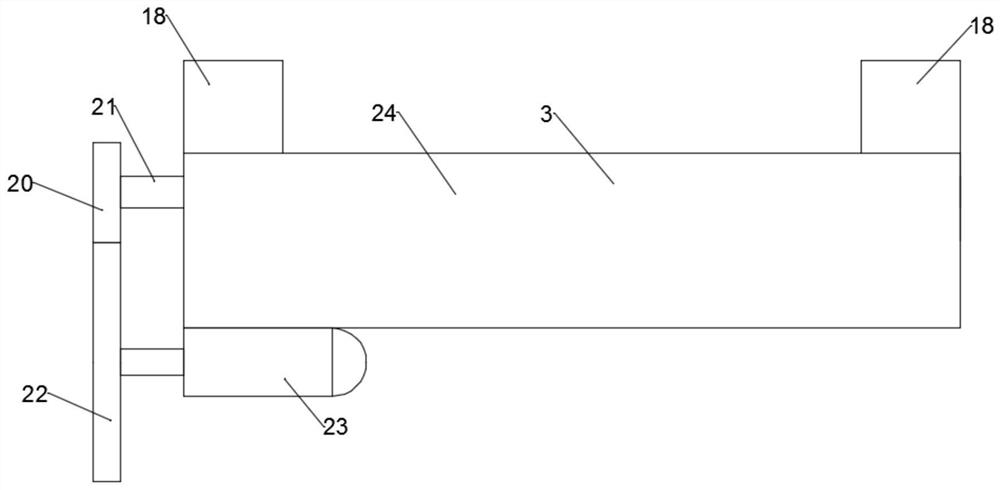
[0026] see image 3 and Figure 4 , a construction site with intelligent load trolley, on the basis of embodiment 1, the splint device 24 is composed of a drive motor 23, a drive wheel 22, a driven wheel 20, a threaded rod 21, a clamp block 18 and a threaded hole 19, The driving motor 23 is connected with the driving wheel 22, the driving wheel 22 is connected with the driven wheel 20, the threaded rod 21 is fixedly arranged on the driven wheel 20, the threaded hole 19 is arranged on the clamp block 18, and the threaded rod 21 It is threadedly connected with the threaded hole 19, and the clamping block 18 is slidingly connected with the stage 3, and the driving wheel 22 is driven by the driving motor 23 to rotate, so as to realize the rotation of the threaded rod 21, and the rotating clamping block 18 of the threaded rod 21 moves, thereby The fixing of the moving block 18 to the installation transfer piece is realized.
PUM
 Abstract
Description
Claims
Application Information
 - R&D
- Intellectual Property
- Life Sciences
- Materials
- Tech Scout
- Unparalleled Data Quality
- Higher Quality Content
- 60% Fewer Hallucinations
Browse by: Latest US Patents, China's latest patents, Technical Efficacy Thesaurus, Application Domain, Technology Topic, Popular Technical Reports.
© 2025 PatSnap. All rights reserved.Legal|Privacy policy|Modern Slavery Act Transparency Statement|Sitemap|About US| Contact US: help@patsnap.com