Iron chipping storage box in factory

A technology for storage boxes and iron filings, applied in the direction of internal accessories, loading/unloading, unloading devices, etc., can solve the problem that the iron filings box is not easy to dump, and achieve the effect of easy movement and simple operation

Active Publication Date: 2020-06-12
林仙夫
View PDF4 Cites 1 Cited by
  • Summary
  • Abstract
  • Description
  • Claims
  • Application Information

AI Technical Summary

Problems solved by technology

[0003] The purpose of the present invention is to provide a storage box for iron filings in the f

Method used


Image

  • Iron chipping storage box in factory
  • Iron chipping storage box in factory
  • Iron chipping storage box in factory

Examples


Embodiment Construction

[0030] In order to clearly illustrate the technical characteristics of this program, the following specific implementation methods, combined with its attached Figures 1 to 11 , the present invention is described in detail. It should be noted that components illustrated in the figures are not necessarily drawn to scale. The present invention omits descriptions of well-known components and well-known technologies in order to avoid unnecessarily limiting the present invention.

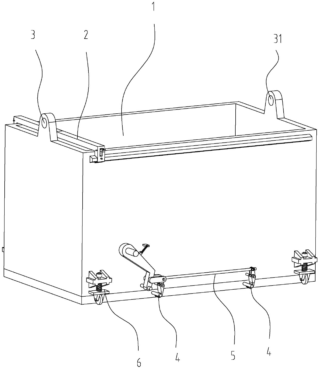
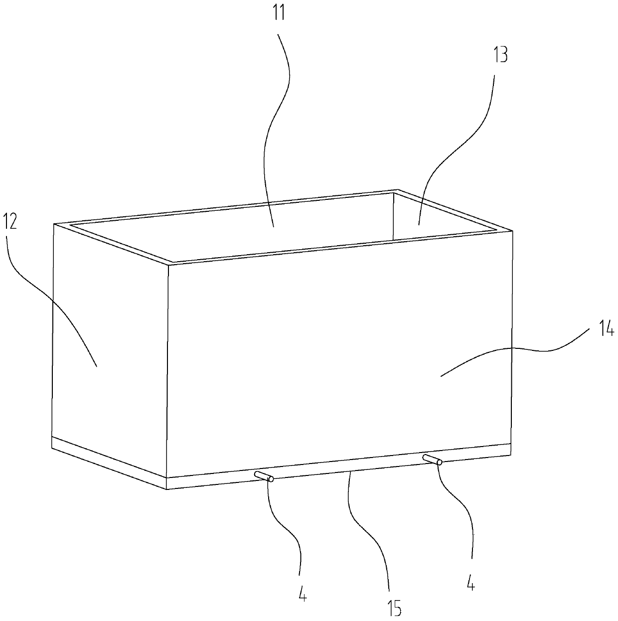
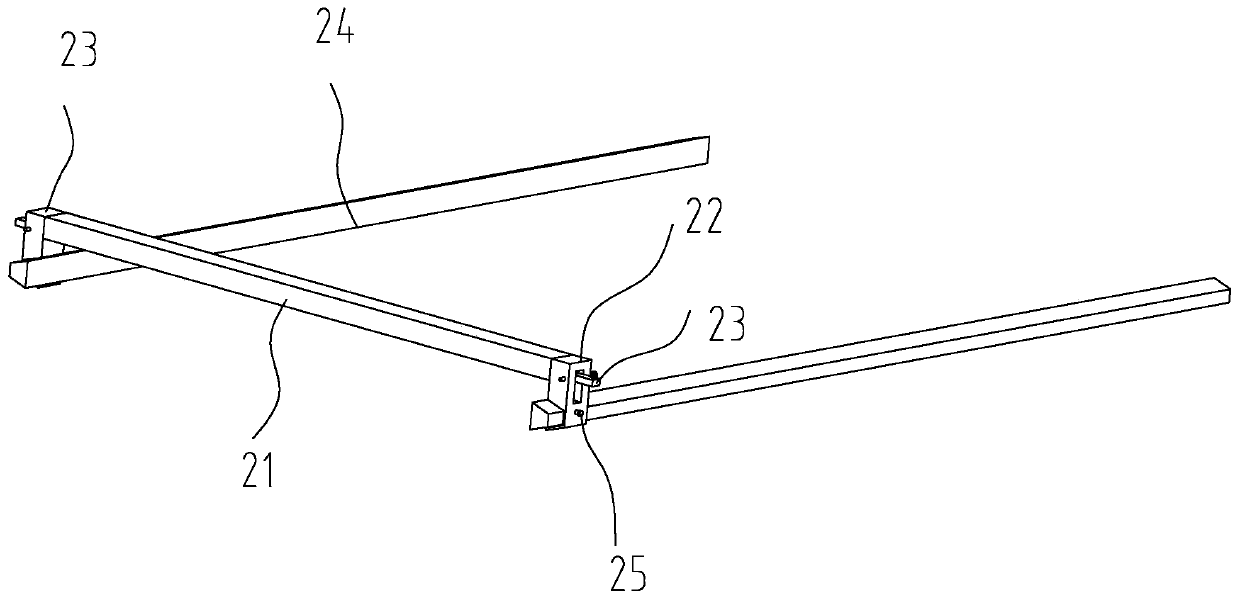
[0031]An iron filings storage box in a factory, including a box body 1, an iron filings laying device 2, a lifting piece 3, a hanging rod 4, a foot-operated opening device 5 and a telescopic walking device 6; the box body 1 includes a front Side plate 11, left side plate 12, right side plate 13, back side plate 14 and lower cover 15, left side plate 12 is fixed on the left side of front side plate 11, and right side plate 13 is fixed on the right side of front side plate 12 , the rear side of the front...


PUM


Abstract

The invention discloses an iron chipping storage box in a factory, and belongs to the technical field of iron chipping storage boxes. The iron chipping storage box in the factory comprises a box body,an iron chipping flatly-spreading device, hoisting elements, hanging rods, a pedaled opening device and telescopic travelling devices, wherein the box body comprises a front side plate, a left side plate, a right side plate, a rear side plate and a lower cover; the left side plate is fixed to the left side of the front side plate; the right side plate is fixed to the right side of the front sideplate; the rear side plate is fixed to the rear side of the front side plate; the lower cover is connected with the lower part of the front side plate through a hinge; two hanging rods are fixed to the rear side surface of the lower cover; the pedaled opening device is arranged on the rear side plate; the pedaled opening device is connected together with the two hanging rods in a hanging manner separately; the telescopic travelling devices are arranged on the lower part of the front side plate and the lower part of the rear side plate separately; the upper part of the front side plate and theupper part of the rear side plate are connected with the iron chipping flatly-spreading device; and the hoisting elements are fixed to the left side plate and the right side plate. The iron chipping storage box in the factory is used for solving the technical problem that the iron chipping box is inconveniently poured.

Description

technical field [0001] The invention relates to the technical field of iron filings storage boxes, in particular to an iron filings storage box in a factory. Background technique [0002] At present, in some mechanical processing workshops, a large amount of iron filings will be generated after various machine tools process parts. After the iron filings are full, it is necessary to hoist the iron filings box to the truck by driving, and then dump the iron filings in the iron filings box; there are basically two ways to pour iron filings in the existing iron filings box, dumping and The bottom-opening and dumping-type chip boxes are extremely inconvenient when dumping, and because the dumping is carried out by driving, the operation is extremely difficult. The bottom-opening chip boxes are generally manually flipped to open the lower cover. Open it, but due to the heavy weight of the chip box after storing the iron filings, a large amount of iron filings will exert great pre...

Claims


Application Information

Patent Timeline
IPC IPC(8): B65D25/24B65D25/52B65D25/02B65G69/04B65G65/40
CPCB65D25/02B65D25/24B65D25/52B65G65/40B65G69/045
Inventor 夏建秋王凯杜航林童童
Owner 林仙夫
Why Eureka
Try Eureka