Boundary protection method for unmanned aerial vehicle with high lift-drag ratio

A boundary protection and unmanned aerial vehicle technology, applied in non-electric variable control, instrument, attitude control, etc., can solve problems such as flight accidents, large changes in control quality, and unmanned aerial vehicle instability, and achieve the effect of protecting flight safety

Active Publication Date: 2020-06-12
CHENGDU AIRCRAFT INDUSTRY GROUP
View PDF20 Cites 1 Cited by
  • Summary
  • Abstract
  • Description
  • Claims
  • Application Information

AI Technical Summary

Problems solved by technology

[0003] However, the pilot is highly dependent on the actual experience of the designer. In addition, its fixed control law parameters lead to large changes in the control quality of the UAV within the full envelope range, especially when the external environment is strongly disturbed. , due to the lack of corresponding protection measures, the airspeed, angular velocity and overload of the UAV will easily exceed its own limit boundary, which will easily cause the UAV to enter an unstable state and affect the flight quality. In severe cases, the aircraft will stall and cause a flight accident

Method used


Image

  • Boundary protection method for unmanned aerial vehicle with high lift-drag ratio
  • Boundary protection method for unmanned aerial vehicle with high lift-drag ratio
  • Boundary protection method for unmanned aerial vehicle with high lift-drag ratio

Examples


Embodiment 1

[0100] A boundary protection method for an unmanned aerial vehicle with a large lift-to-drag ratio. A boundary protection item is added to the attitude driving control loop, and the boundary protection item is the product of the error value of the protected signal and the gain K.

Embodiment 2

[0102] A boundary protection method for a UAV with a large lift-to-drag ratio, including airspeed boundary protection, angular velocity boundary protection, and overload boundary protection, adding a boundary protection item to the attitude driving control loop, and the boundary protection item is the error value of the protected signal Product with gain K.

[0103] The invention aims to overcome the deficiencies of the airspeed, angular velocity and overload exceeding the limits of the attitude pilot after being strongly disturbed. The airspeed boundary protection introduces an airspeed boundary protection item in the inner loop control target pitch angle setting. The angular velocity boundary protection includes two links of feedforward compensation and feedback compensation; the feedforward compensation is to ensure that the error value of the inner loop attitude angle for two consecutive beats is not greater than a certain limit value; the feedback compensation is to contr...

Embodiment 3

[0106] The present embodiment optimizes on the basis of embodiment 1 or 2, and the content of airspeed boundary protection is as follows:

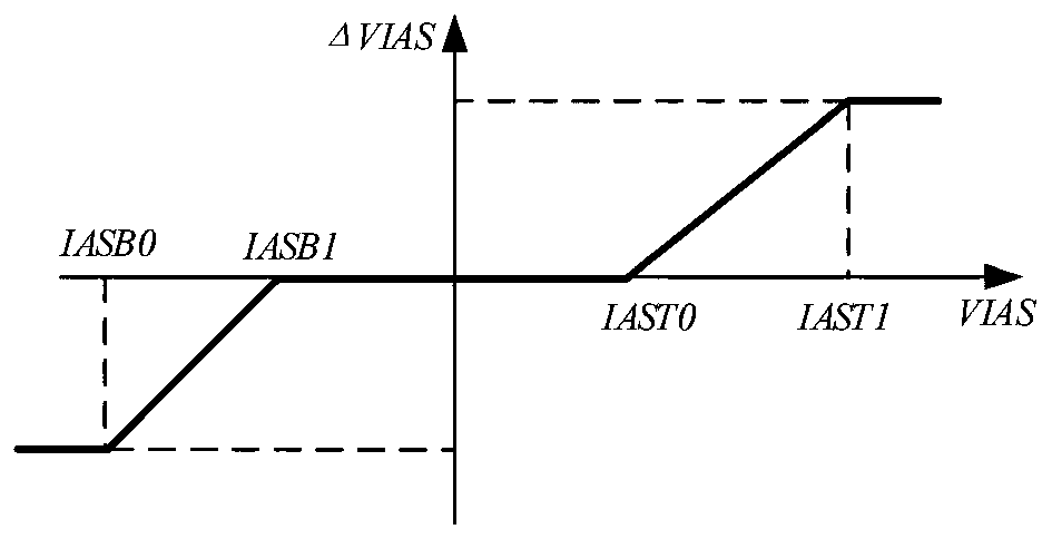
[0107] The airspeed boundary protection technique is in the longitudinal elevator control loop θ g The airspeed boundary protection item is added to realize the airspeed protection, and its specific control law structure is The error signal is defined as ΔVIAS, and the airspeed boundary protection range is as follows figure 1 shown.

[0108] 1) When indicated airspeed VIAS≤IASB0: ΔVIAS=IASB0-IASB1;

[0109] 2) When the indicated airspeed IASB0

[0110] 3) When the indicated airspeed IASB1

[0111] 4) When the indicated airspeed IAST0

[0112] 5) When the indicated airspeed IAST1

[0113] The basic principle is that when the UAV is disturbed, the airspeed is greater than (less than) the speed protection boundary value, through th...


PUM


Abstract

The invention discloses a boundary protection method for an unmanned aerial vehicle with a large lift-drag ratio, and the method comprises the step: adding a boundary protection item which is the product of an error value of a protected signal and a gain K into an attitude driving control loop; according to the method, boundary protection control is added on the basis of not changing the originalcontrol law structure, and when each signal exceeds the boundary, each signal can be ensured to enter the protected range again by quickly adjusting the flight attitude, so that the flight safety of the unmanned aerial vehicle is protected.

Description

technical field [0001] The invention belongs to the technical field of unmanned aerial vehicles, and in particular relates to a boundary protection method for an unmanned aerial vehicle with a large lift-to-drag ratio. Background technique [0002] At present, most UAVs with a large lift-drag ratio use attitude pilots, which generally adopt the mainstream PID control scheme. The inner loop of the controller is attitude angle control, and the outer loop is trajectory control. The controller structure is simple and clear, and the control The effect is good, and it is easy to implement in engineering. [0003] However, the pilot is highly dependent on the actual experience of the designer. In addition, its fixed control law parameters lead to large changes in the control quality of the UAV within the full envelope range, especially when the external environment is strongly disturbed. , due to the lack of corresponding protection measures, the airspeed, angular velocity and ove...

Claims


Application Information

Patent Timeline
Patent Type & Authority Applications(China)
IPC IPC(8): G05D1/08G05D1/10
CPCG05D1/0808G05D1/101
Inventor 赵东宏金波张瞿辉熊维康夏炎
Owner CHENGDU AIRCRAFT INDUSTRY GROUP
Why Eureka
Try Eureka