
Unmanned aerial vehicle strong electromagnetic pulse protection system and experimental method thereof

A protection system and electromagnetic protection technology, applied in aircraft lighting protectors, aircraft electrostatic dischargers, emergency protection circuit devices for limiting overcurrent/overvoltage, etc., can solve the problem of inability to effectively deal with strong electromagnetic pulse interference There are problems such as higher requirements and increased damage costs of drones, so as to achieve the effect of convenient environment construction, guaranteed flight safety, and high protection efficiency

Pending Publication Date: 2021-03-05
国网甘肃省电力公司超高压公司
View PDF2 Cites 0 Cited by
  • Summary
  • Abstract
  • Description
  • Claims
  • Application Information

AI Technical Summary

Problems solved by technology

[0003] The existing EMP protection schemes for UAVs are mainly system-level rectification suggestions, which cannot effectively deal with the interference of strong EMP
For example, in UHV line inspection operations, the current drones can only maintain a relatively long flight safety distance, which is not conducive to the accuracy of line inspection observation, and the line inspection efficiency is low
And there are higher requirements for the shooting lens, resulting in higher solution costs
In uncontrollable situations, such as lightning electromagnetic pulse interference, it is likely to directly cause a crash, which increases the damage cost of the drone

Method used


Image

  • Unmanned aerial vehicle strong electromagnetic pulse protection system and experimental method thereof
  • Unmanned aerial vehicle strong electromagnetic pulse protection system and experimental method thereof
  • Unmanned aerial vehicle strong electromagnetic pulse protection system and experimental method thereof

Examples


Embodiment Construction

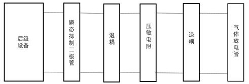
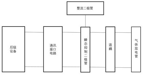
[0029] Such as Figure 1-3 As shown, a UAV strong electromagnetic pulse protection system of the present invention includes a power supply protection module, a communication protection module and a radio frequency protection module; the power supply protection module includes a gas discharge tube, a piezoresistor and a transient suppression diode, and the gas discharge tube The varistor is electrically connected to the varistor, the varistor is electrically connected to the transient suppression diode, and the transient suppression diode is electrically connected to the power port of the drone. The three-level protection circuit composed of the power protection module.

[0030] Further, the power supply protection module includes a decoupling resistor, the decoupling resistor is electrically connected between the gas discharge tube and the piezoresistor, and the decoupling resistor is electrically connected between the piezoresistor and the transient suppression diode.

[003...


PUM


Abstract

The invention relates to the technical field of unmanned aerial vehicle safety protection, in particular to an unmanned aerial vehicle strong electromagnetic pulse protection system and an experimental method thereof. The unmanned aerial vehicle strong electromagnetic pulse protection system comprises a power supply protection module, a communication protection module and a radio frequency protection module. The power supply protection module comprises a gas discharge tube, a piezoresistor and a transient suppression diode, the radio frequency protection module comprises a branch electromagnetic protection module, and the communication protection module comprises a gas discharge tube and a transient suppression diode. Indirect effects generated by strong electromagnetic pulses enter an unmanned aerial vehicle system through conduction coupling, radiation coupling and other modes, damage is caused to electronic device in the unmanned aerial vehicle, and threats such as unmanned aerial vehicle positioning failure, flight control failure and communication blocking are caused. The flight safety of the unmanned aerial vehicle in a severe electromagnetic environment is effectively protected, each module is of a plug-in structure, and the use convenience is guaranteed while the protection effect is guaranteed.

Description

technical field [0001] The invention relates to the technical field of UAV safety protection, in particular to a UAV strong electromagnetic pulse protection system and an experimental method thereof. Background technique [0002] With the maturity of drone technology, the application range of drones is getting wider and wider, and the flying environment of drones is becoming more and more complex. Most of the existing drones have a general electromagnetic interference protection design, such as using shielded wires, installing flow guide strips, and processing holes, etc. These measures can ensure the flight safety of drones in general electromagnetic interference, but for strong Electromagnetic pulse interference, such as lightning electromagnetic pulse, weapon-grade electromagnetic pulse, and electromagnetic pulse generated by UHV power grid, etc., is difficult to achieve high-level protection. For example, in "Electromagnetic Protection Technology for UAVs in Strong Elec...

Claims


Application Information

Patent Timeline
Patent Type & Authority Applications(China)
IPC IPC(8): H02H9/00G01R31/00B64D45/00B64D45/02
CPCH02H9/00H02H9/005G01R31/001B64D45/00B64D45/02
Inventor 侯清川焦小强王文卓侯建强黄政峰
Owner 国网甘肃省电力公司超高压公司
Learn More