
Differential hydraulic damper

A hydraulic damper and damping chamber technology, applied in the field of hydraulic dampers, can solve problems such as unequal damping force, unstable damping performance, and untimely oil replenishment, so as to reduce pressure loss, eliminate abnormal vibration, and enhance oil replenishment effect of ability

Active Publication Date: 2020-08-07
SICHUAN LINGFENG AVIATION HYDRAULIC MACHINERY
View PDF7 Cites 0 Cited by
  • Summary
  • Abstract
  • Description
  • Claims
  • Application Information

AI Technical Summary

Problems solved by technology

[0003] The purpose of the present invention is to address the shortcomings of the prior art, to solve the problem that the damping force of the hydraulic damper in the prior art is not adjustable and the scope of application is small; the damping force in the stretching and compressing directions is not equal; the damping performance is unstable; the damping can be adjusted The small flow rate of the component is poor; the oil replenishment valve is affected by its opening force, and the oil replenishment is not timely and other technical problems. It provides a stable damping performance, adjustable damping coefficient, equal damping force in the direction of tension and compression, wide application range and good adaptability. Differential structure of differential hydraulic damper with adjustable damping coefficient

Method used


Image

  • Differential hydraulic damper
  • Differential hydraulic damper
  • Differential hydraulic damper

Examples


Embodiment Construction

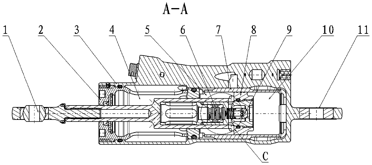
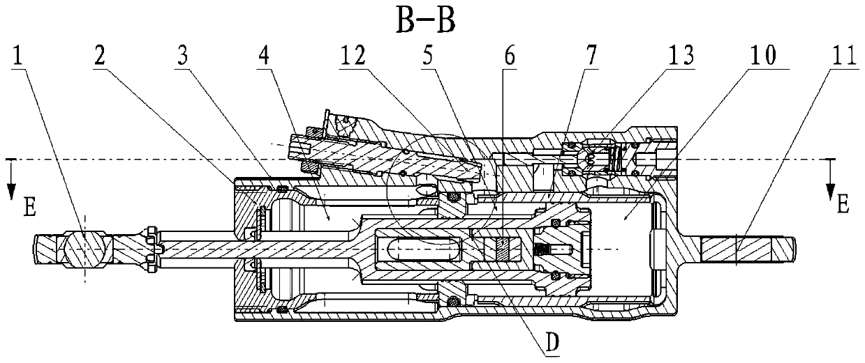
[0024] see Figure 1-Figure 7, In the embodiment described below, a differential hydraulic damper includes: an outer cylinder 3 with an outer cylinder earring 11, an oil replenishing cavity sealed in the limiting cavity of the outer cylinder 3 through an end cover 2 and its annular seal 4. Through the differential chamber inner cylinder 7 separated by the sealing partition wall at the cylinder end of the oil supply chamber 4, through the end cover 2 and the assembly hole of the sealing partition wall, the reciprocating motion is restricted in the oil supply chamber 4 and the differential chamber inner cylinder 7 the piston rod 1. The piston rod 1 with the earring joint has a connecting hollow extension body and a damping piston 8 connected to its free end wall on the journal end. In the stepped hole, the series ring damping valve 6 separated from each other and the one-way check valve 9 assembled in the center of the stepped hole at the shaft end of the damping piston 8, the ...


PUM


Abstract

The invention discloses a differential hydraulic damper and aims at providing an adjustable pressure damper which is stable in damping property, and adjustable in damping coefficient. According to thetechnical scheme, a damping piston changes the volume between a rod damping cavity and a rodless damping cavity to transmit pressure of hydraulic fluid, continuous circulation is carried out to exertreverse acting force, on or off of a one-way check valve is controlled, one-way flowing of hydraulic fluid of the rod damping cavity, the rodless damping cavity and an oil supplementing cavity is achieved, the pressure, the differential volume and the compression ratio in a left cavity and a right cavity of an inner cylinder of the differential cavity can be selectively controlled, meanwhile, through any-time adjusting of an outer adjustable damping oil path formed by an adjustable damping valve rod assembled in the generatrix direction of an outer cylinder and extending into the rod dampingcavity in an inclined manner and a relatively-assembled oil supplementing one-way check valve, in-time oil supplementing is started through hydraulic fluid pressure of the rod damping cavity, flowingof the hydraulic fluid, part of pressure transmission for controlling the damping property and the back and forth vibration running stroke of a piston rod output shaft can be controlled, and the damping effect is achieved.

Description

technical field [0001] The invention relates to a small-hole throttle type hydraulic damper with a linear single-rod differential structure. The damping coefficient can be adjusted by changing the size of the damping hole as required, and the damper can automatically replenish hydraulic fluid. Examples that can be used include aviation, aerospace, automotive, construction, road, bridge, railway and other industries, in mechanical engineering, ground motion vehicles, aircraft control systems, etc. Background technique [0002] When many mechanisms are in mechanical motion, due to the influence of external force, vibration and impact will occur, which will reduce the working efficiency of the mechanical system, affect the service life, and damage the mechanical structure in severe cases. Instability, even resonance occurs, destroying the mechanism. In order to reduce the influence of these phenomena on the mechanism, damping devices that can effectively protect the mechanism...

Claims


Application Information

Patent Timeline
Patent Type & Authority Patents(China)
IPC IPC(8): F16F9/19F16F9/44
CPCF16F9/19F16F9/446
Inventor 袁洪回郭智侯中志高泽宇颜若飞
Owner SICHUAN LINGFENG AVIATION HYDRAULIC MACHINERY
Learn More