Separately excited direct-current motor

A technology of DC motor and DC power supply, which is applied in the direction of DC commutator, electrical components, electromechanical devices, etc., and can solve the problems that are difficult to deal with the investigation technology, affect the economic construction and national defense construction, restrict and influence, etc.

Inactive Publication Date: 2020-06-12
UNIV OF SHANGHAI FOR SCI & TECH
View PDF3 Cites 0 Cited by
  • Summary
  • Abstract
  • Description
  • Claims
  • Application Information

AI Technical Summary

Problems solved by technology

At present, the traditional separately excited DC motors used in high-power national defense electric equipment have been difficult to cope with the increasingly advanced detection technology
[0006] Based on the above reasons, the development of separately excited DC motors has been restricted and affected, which has affected economic construction and national defense construction.

Method used


Image

  • Separately excited direct-current motor
  • Separately excited direct-current motor
  • Separately excited direct-current motor

Examples


Embodiment Construction

[0035] The specific implementation manners of the present invention will be described below in conjunction with the accompanying drawings.

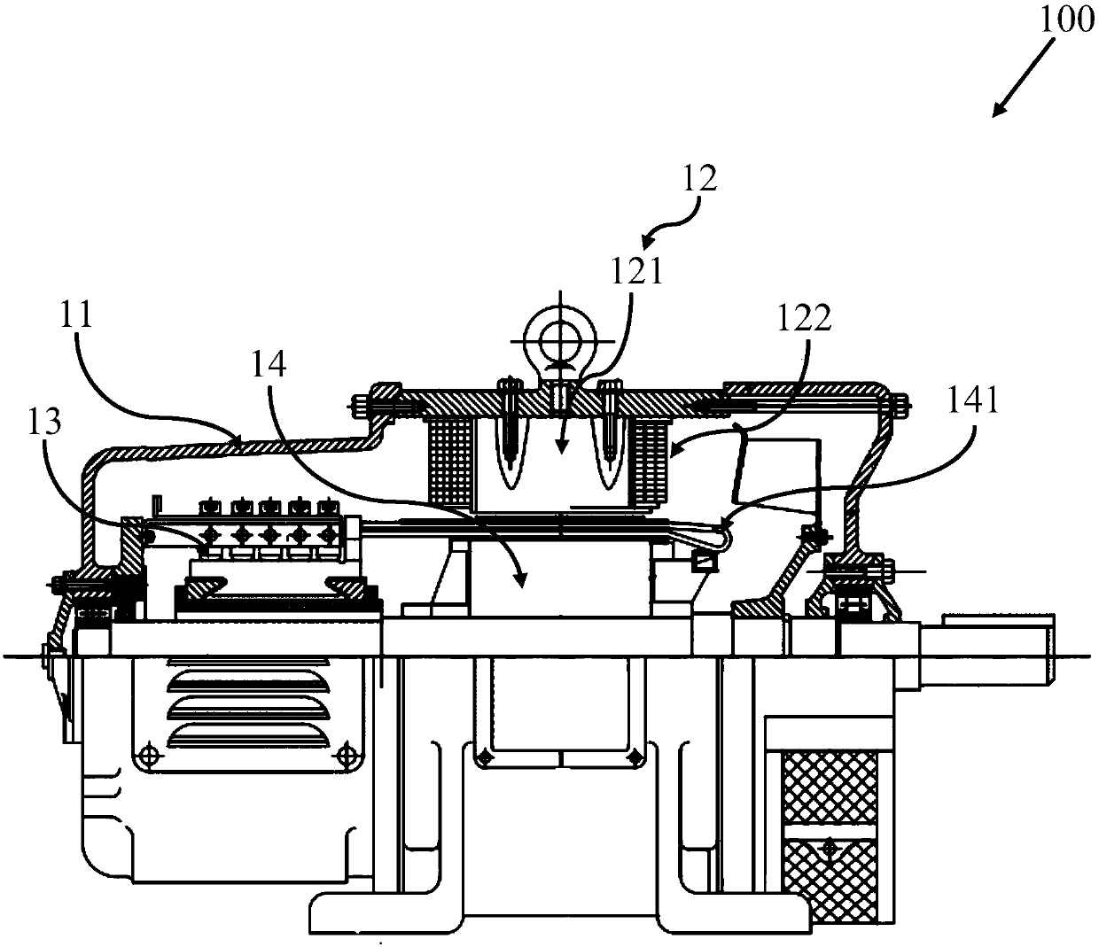
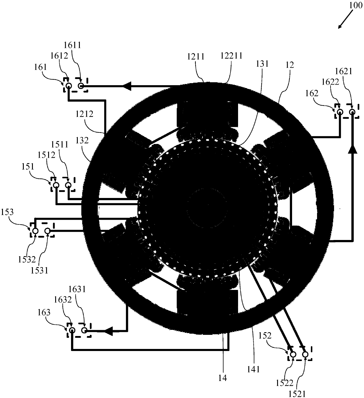
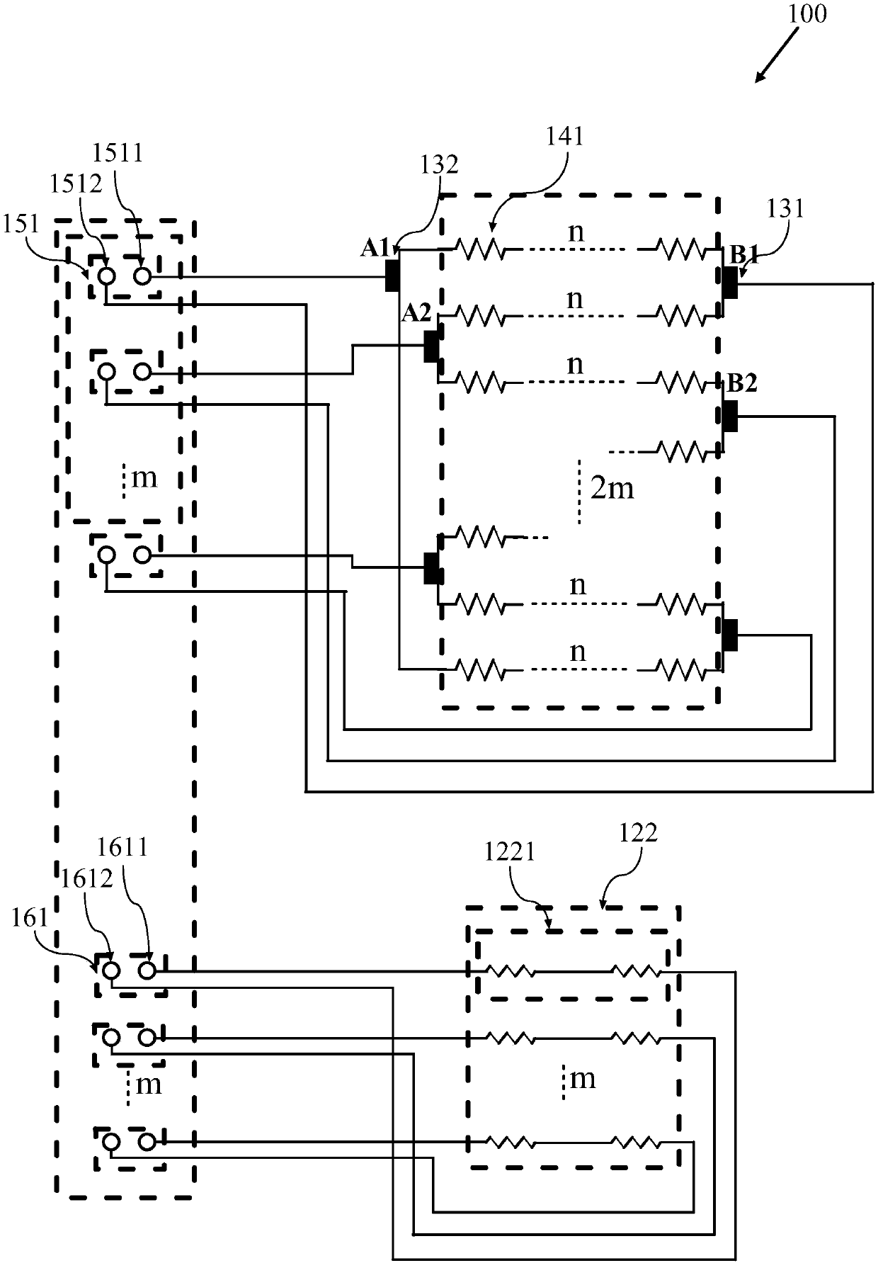
[0036] figure 1 It is a schematic diagram of the longitudinal section structure of the separately excited DC motor in the embodiment of the present invention; figure 2 It is a schematic diagram of a transverse cross-sectional structure of a separately excited DC motor in an embodiment of the present invention; image 3 It is a schematic diagram of the circuit connection of the armature winding and the field winding of the separately excited DC motor of the present invention; Figure 4 It is a schematic diagram of the circuit connection of the armature winding and the field winding of the separately excited DC motor in the embodiment of the present invention; Figure 5 It is a schematic diagram of the single-stack connection of the armature windings of the separately excited DC motor in the embodiment of the present invention.

[0037]...


PUM


Abstract

The invention provides a separately excited direct-current motor, which is connected with m pairs of first power output terminals formed by at least one first direct-current power supply and m pairs of second power output terminals formed by at least one second direct-current power supply, and comprises a casing, m pairs of brushes; a stator including m pairs of main magnetic poles corresponding to the m pairs of brushes and including one excitation winding portion; and a rotor, the excitation winding part comprises m excitation winding units corresponding to the m pairs of main magnetic polesrespectively. The insulating conductor strip in each excitation winding unit is provided with one end and the other end; the m first armature wiring terminals and the m second armature wiring terminals respectively and correspondingly form m pairs of armature external wiring terminals; the armature external wiring terminals are used for being connected with the m pairs of first power supply output terminals in a one-to-one correspondence mode, the m first excitation terminals and the m second excitation terminals correspondingly form m pairs of excitation external terminals respectively, them excitation external terminals are used for being connected with the m pairs of second power supply output terminals in a one-to-one correspondence mode, and m is a positive integer not smaller than2.

Description

technical field [0001] The invention belongs to the field of DC motors, in particular to a separately excited DC motor. Background technique [0002] The excitation winding and the armature winding of the separately excited DC motor are powered by two power sources respectively, and the excitation current is provided independently, which has nothing to do with the armature current. Therefore, the control of the separately excited DC motor is convenient, and it is easy to realize speed regulation, positive and negative rotation and energy feedback. Widely used in electric forklifts, electric cars, electric sightseeing cars, electric tractors, large machine tool spindle drive systems and ships, etc. [0003] A DC motor is generally used together with a chopper to form a DC motor speed control device. In order to ensure system reliability, the maximum output current of the chopper is generally 2 to 3 times the rated current of the motor. High-power and high-performance DC mot...

Claims


Application Information

Patent Timeline
Patent Type & Authority Applications(China)
IPC IPC(8): H02K23/12H02K23/36H02K23/38H02K3/18
CPCH02K3/18H02K23/12H02K23/36H02K23/38
Inventor 金爱娟李少龙
Owner UNIV OF SHANGHAI FOR SCI & TECH
Why Eureka
Try Eureka