Joint distraction device

A technology of spreader and joint, applied in the field of joint spreader, can solve the problem that joint space cannot be opened minimally, and achieve the effect of reducing burden, increasing joint space and ensuring reliability

Pending Publication Date: 2020-06-16
XIEHE HOSPITAL ATTACHED TO TONGJI MEDICAL COLLEGE HUAZHONG SCI & TECH UNIV
View PDF0 Cites 0 Cited by
  • Summary
  • Abstract
  • Description
  • Claims
  • Application Information

AI Technical Summary

Problems solved by technology

[0005] In view of the above problems, the present invention provides a joint distractor, w

Method used


Image

  • Joint distraction device
  • Joint distraction device
  • Joint distraction device

Examples


Embodiment 1

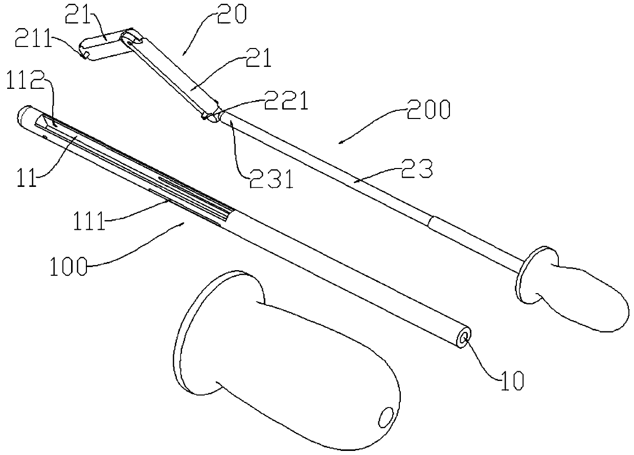
[0049] Such as Figure 1-3 As shown, wherein one end of the main body 100 is provided with a receiving groove 11, and the other end is provided with a central sliding cavity 10;

[0050] Both ends of the expansion portion 20 are located in the receiving groove 11,

[0051] The expansion end 231 passes through the sliding cavity 10 and is connected to the expansion portion 20.

[0052] A limiting groove 111 is provided at one end of the receiving groove 11 close to the sliding cavity 10;

[0053] An end of the spreading portion 20 close to the spreading end 231 is provided with a limiting block 221 matching the limiting groove 111.

[0054] The end of the spreading portion 20 away from the spreading end 231 is rotatably connected to the end of the receiving groove 11 away from the sliding cavity 10.

[0055] The expansion portion 20 is composed of a plurality of mutually hinged extension portions 21; the expansion portion 20 can be completely located in the receiving groove 11 after being...

Embodiment 2

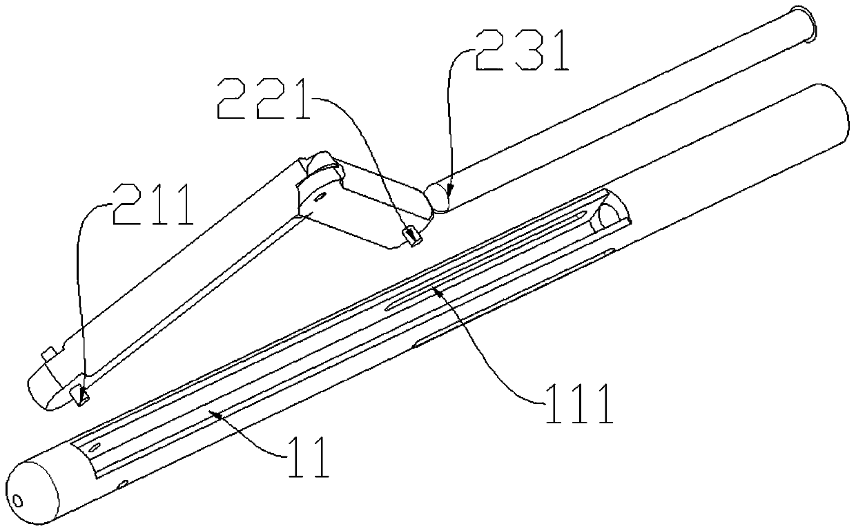
[0059] Such as Figure 4-5 As shown, wherein, the main body part 100 is of a through structure, and the length of the movable part 23 is greater than that of the main body part 100;

[0060] The expansion end 231 passes through the movable cavity 10 and is connected to the expansion portion 20.

[0061] The end of the expansion portion 20 away from the expansion end 231 is connected to the stretching end 103 of the main body 100.

[0062] After the expansion portion 20 is folded, the outer diameter of the expansion portion 20 is less than or equal to the outer diameter of the main body 100.

[0063] The movable part 23 is provided with a handle at one end away from the expansion part 20, and the main body part 100 is sleeved outside the movable part 23 between the expansion part 20 and the handle.

[0064] The first main body 101 and the second main body 102 of the main body 100 are rotatably connected, and the two can rotate relatively;

[0065] The first main body 101 and the expansion...

Embodiment 3

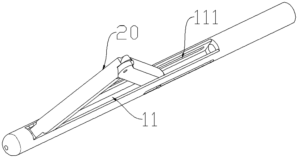
[0073] Such as Image 6 As shown in this embodiment, the main structure is similar to the second embodiment. The expansion part 20 of the three-dimensional network structure is composed of several expansion units, and each expansion unit is composed of mutually hinged expansion parts 21. When opened, each expansion unit is opened separately.

[0074] One method of use in this embodiment is:

[0075] When the first main body part 101 is rotated so that the main body part 100 moves to the distal end and the spreading part 200 moves to the distal end, the stretching end 103 squeezes the proximal end of the spreading part 20 to the distal end, so that the mutually hinged stretching parts 21 The distance of the distal end is reduced, so that the stretched portion 21 is partially stretched outwards, so that the outer diameter of the stretched portion 20 is increased, which plays a role of spreading.


PUM


Abstract

The invention relates to a joint distraction device which comprises a main body part and a distraction part partially located in the main body part, and the distraction part can move in the main bodypart in the length direction, and comprises a movable piece, the distraction end of the movable piece is connected to a distraction part, and the end, away from the distraction end, of the distractionpart is connected to the main body part; and the movable piece drives the distraction part to open and close when moving relative to the main body piece. The joint distraction device has the beneficial effects that the overall outer diameter of the device is small when the device is folded, and the device can enter the shoulder from a small wound to be locally unfolded inside; the wound is smaller, and the burden of a patient is reduced.

Description

Technical field [0001] The invention relates to the technical field of joint surgery tools, in particular to a joint expander. Background technique [0002] Subacromial impingement ( Figure 8 ) Is a common clinical disease that causes shoulder joint pain and dysfunction. Abnormal morphology of the anterior and lateral ends of the acromion, osteophyte formation, osteophyte formation of the greater tuberosity of the humerus, and other possible causes of the reduction of the acromion-humeral head distance can cause compression and impact of the subacromial structure. This impact mostly occurs between the anterior and outer 1 / 3 of the acromion and the humeral head (mainly the greater tuberosity of the humerus). Repeated impacts promote damage and degeneration of the bursa and tendon, and even rupture of the tendon (rotator cuff). The definition of impact sign is: the subacromial joint due to anatomical structure or dynamics, during the lifting and abduction of the shoulder, the cli...

Claims


Application Information

Patent Timeline
IPC IPC(8): A61B17/02
CPCA61B17/0218A61B17/025A61B2017/564
Inventor 何宇王洪孟春庆
Owner XIEHE HOSPITAL ATTACHED TO TONGJI MEDICAL COLLEGE HUAZHONG SCI & TECH UNIV
Why Eureka
Try Eureka