Minimally invasive centrally-mounted hollow screw extractor

A hollow screw and extractor technology, applied in fixers, medical science, surgery, etc., can solve problems such as inability to withdraw, twist and slip, and inability to fully reveal the tail end of the hollow screw, so as to achieve the effect of convenient operation and avoid twist and slip

Pending Publication Date: 2020-06-16
青岛山大齐鲁医院(山东大学齐鲁医院(青岛))
View PDF0 Cites 1 Cited by
  • Summary
  • Abstract
  • Description
  • Claims
  • Application Information

AI Technical Summary

Problems solved by technology

However, due to minimally invasive insertion, the tail end of the hollow nail cannot be fully exposed when it is taken out. The usual method is to expose the tail cap of the hollow nail through a large incision. The end of the hollow nail is generally in the shape of a hexagonal prism
Under the current situation, the hollow nail is directly taken out with an ordinary screwdriver, which requires force along the direction of the hollow nail, and the pulling operation is very inconvenient. Because the fracture has healed, the hollow nail will be squeezed by the surrounding bone, often deformed and twisted. slippery or unable to exit situations

Method used


Image

  • Minimally invasive centrally-mounted hollow screw extractor
  • Minimally invasive centrally-mounted hollow screw extractor
  • Minimally invasive centrally-mounted hollow screw extractor

Examples


Embodiment Construction

[0018] Now in conjunction with the accompanying drawings, the preferred embodiments of the present invention will be described in detail.
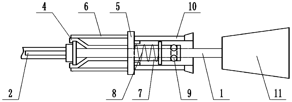
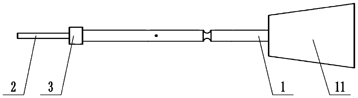
[0019] The design idea of ​​this application is that the small local incision does not need to expose the hollow nail tail cap. Under minimally invasive operation, the center of the hollow nail can be detected by using the front guide rod, and can be inserted quickly and accurately along the center of the hollow nail channel. After the end cap, rotate a little, apply the specially designed engaging structure to fix the end of the hollow nail, rotate and fully force along the direction of the hollow nail, and take out the hollow nail directly with the extractor. The whole operation is minimally invasive, concise and accurate

[0020] A minimally invasive central hollow screw extractor, such as Figure 1 to Figure 3 As shown, it includes a polished rod 1, a guide rod 2, a block 3, a ferrule 4, a push plate 5, a sleeve 6, a slider 7, a sprin...


PUM


Abstract

The invention discloses a minimally invasive centrally-mounted hollow screw extractor, and relates to the related technical field of hollow screws for operations. An annular groove is arranged in themiddle of a polished rod; a guide rod is arranged at the front end of the polished rod and used for inserting a hollow nail; a clamping block is arranged at the joint of the polished rod and the guiderod; a clamping sleeve is arranged on the polished rod, and a buckle corresponding to the clamping block is arranged at the front end of the clamping sleeve; a push plate is movably arranged on the outer side of the polished rod; a sleeve is arranged at the front end of the push plate and used for controlling opening and closing of the buckle; a sliding block is movably arranged on the outer sideof the polished rod, and a ball hole communicated with the inner cavity is formed in the rear end of the sliding block; one end of a spring is connected with the polished rod, and the other end of the spring is connected with the rear end of the push plate; a ball is arranged in the ball hole of the sliding block; and a push sleeve is arranged on the outer side of the polished rod and the outer side of the sliding block and installed at the rear end of the push plate. The invention has the following beneficial effects that: when the clamping block and the clamping sleeve are combined, the endof the hollow nail can be fixed; then the hollow nail can be taken out through a grab handle; and the whole operation process is minimally invasive, convenient and rapid.

Description

technical field [0001] The invention relates to the related technical field of hollow nails for surgery, in particular to a minimally invasive central hollow screw extractor. Background technique [0002] Nowadays, due to traffic accidents, accidents and other reasons, the incidence of fractures continues to increase. With the continuous development of minimally invasive technology, for the treatment of fractures, it is necessary to fix and connect the two ends of the fracture through a minimally invasive method through a hollow nail. In order to make the hollow nail in a good position in the bone and improve the accuracy of the hollow nail position, usually choose The positioning of the guide pin is fixed. How to use: After the successful reset, insert the guide pin minimally invasively. The position is good under fluoroscopy. Screw the hollow nail along the guide pin to play a stabilizing role. After the bone docking is completed, remove the hollow nail. However, due to ...

Claims


Application Information

Patent Timeline
Patent Type & Authority Applications(China)
IPC IPC(8): A61B17/92
CPCA61B17/92A61B2017/564A61B2017/925A61B2017/928
Inventor 亢世杰刘涛王亚成
Owner 青岛山大齐鲁医院(山东大学齐鲁医院(青岛))
Why Eureka
Try Eureka