

High-precision mechanical arm for lathe and working method thereof
A mechanical arm and high-precision technology, which is applied in the direction of manipulators, program-controlled manipulators, metal processing machinery parts, etc., can solve the problems of lathe safety accidents, low accuracy and movement efficiency, and reduce the working efficiency of lathes, so as to avoid safety accidents , the effect of improving safety
- Summary
- Abstract
- Description
- Claims
- Application Information
AI Technical Summary
Problems solved by technology
Method used
Image

Examples
Embodiment Construction
[0038] The following will clearly and completely describe the technical solutions in the embodiments of the present invention with reference to the accompanying drawings in the embodiments of the present invention. Obviously, the described embodiments are only some, not all, embodiments of the present invention. Based on the embodiments of the present invention, all other embodiments obtained by persons of ordinary skill in the art without creative efforts fall within the protection scope of the present invention.
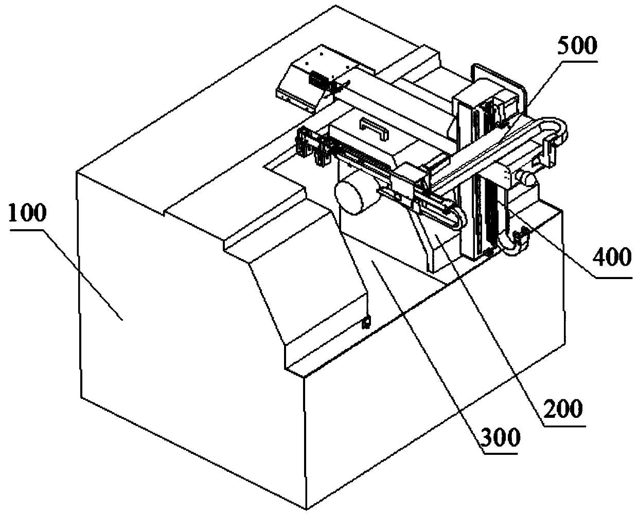
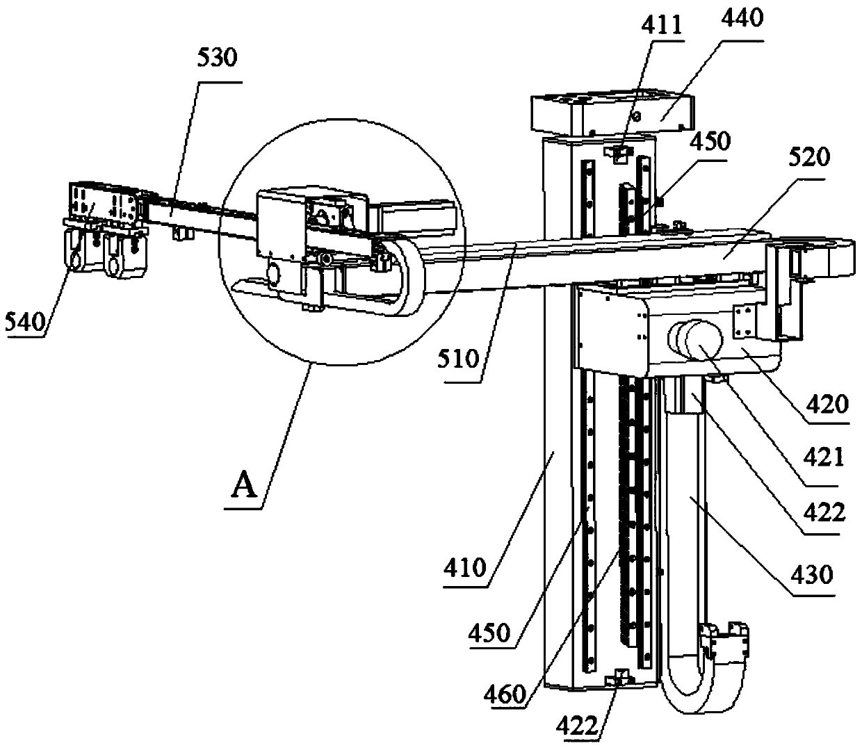
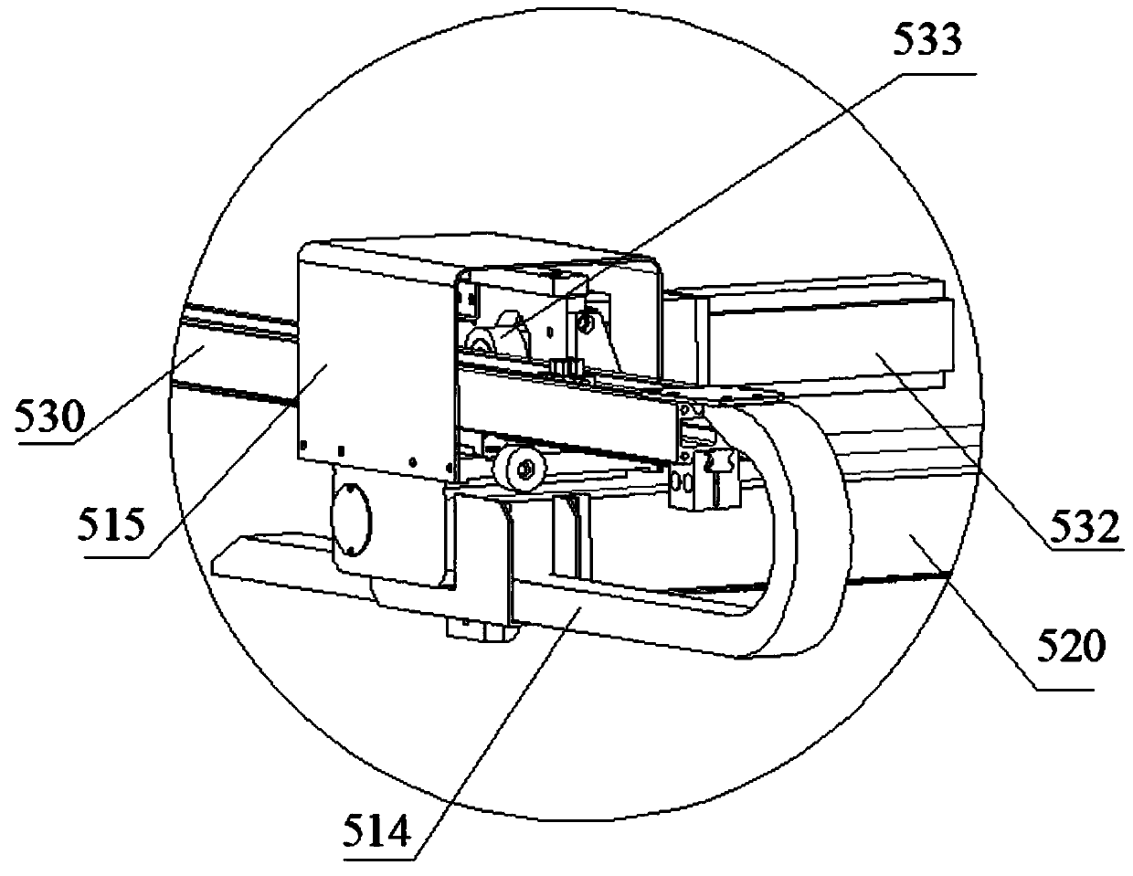
[0039] see Figure 1-9 As shown, the present embodiment provides a high-precision mechanical arm for a lathe, including a support 200 disposed on the table of the lathe 100, a Y-axis mechanical arm 400 disposed at one end of the support 200, and close to the side wall of the working area 300 on the lathe 100 , the X-axis clamping robot 500 provided on the Y-axis robot 400 away from the outside of the bracket 200 . The mechanical arm is used to clamp the parts to b...
PUM
 Abstract
Description
Claims
Application Information