A demoulding tooling and demoulding method for multi-wall box-section structural composite parts

A box section and tooling technology is applied in the field of demoulding tooling for multi-wall box section structural composite parts, which can solve the problems of inability to demold well, large adhesion between the part and the core mold, and large contact area. , to achieve the effect of simple structure, easy demoulding and safe operation

Active Publication Date: 2021-09-03
CETC WUHU DIAMOND AIRCRAFT MFG
View PDF0 Cites 0 Cited by
  • Summary
  • Abstract
  • Description
  • Claims
  • Application Information

AI Technical Summary

Problems solved by technology

[0002] With the development of unmanned aerial vehicle technology, the design of unmanned structural aircraft puts forward higher requirements for its high performance and low weight, while composite materials have low density, high specific strength, high specific modulus, good high and low temperature resistance, and Corrosion and other advantages, so in the structural design of the UAV, its components are designed as a composite material structure, such as the main load-bearing part of the UAV's wing is designed as a carbon fiber composite part with a multi-wall box structure, and many The structural composite parts of the wall box section are faced with the difficulty of demoulding during production and manufacture. Since the part tightly wraps the mandrel, the contact area is large, and the adhesion between the part and the mandrel is very strong. The existing method is not good. for demoulding

Method used


Image

  • A demoulding tooling and demoulding method for multi-wall box-section structural composite parts
  • A demoulding tooling and demoulding method for multi-wall box-section structural composite parts
  • A demoulding tooling and demoulding method for multi-wall box-section structural composite parts

Examples


Embodiment Construction

[0037] The present invention will be described in further detail below in conjunction with the accompanying drawings.

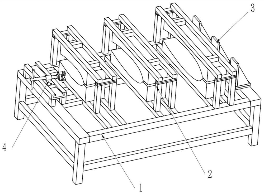
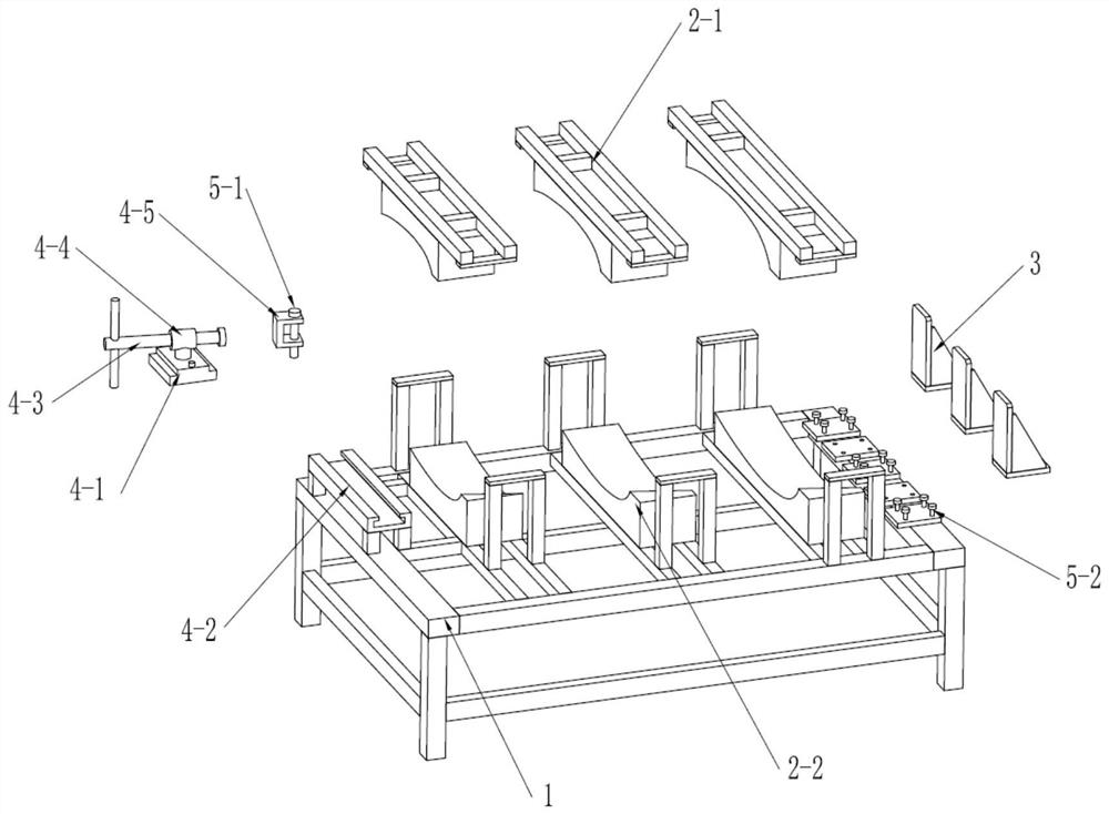
[0038] Such as Figure 1-4 As shown, a demoulding tooling for multi-wall box-section structural composite parts. The tooling includes five parts: a bottom frame 1, a pressure plate assembly 2, a stopper assembly 3, an ejection mechanism 4, and a positioning connector.

[0039] The pressing plate assembly is composed of an upper pressing plate 2-1, a lower pressing plate 2-2, and a silica gel sheet. The upper and lower pressing plates are made of wood, and its profile is consistent with the shape of the workpiece.

[0040] The ejector mechanism 4 is composed of T-shaped slot 4-2, T-shaped block 4-1, screw rod 4-3, nut 4-4, and C-shaped top block 4-5. The T-shaped block can slide along the T-shaped slot, and the nut is connected It can be rotated on the T-shaped block, and the position and direction of the screw rod can be adjusted by moving the T-shaped block...


PUM

PropertyMeasurementUnit
thicknessaaaaaaaaaa

Abstract

The invention belongs to the field of material preparation, and in particular relates to a demoulding tool and a demoulding method for a multi-wall box segment structural composite part. The demoulding tool is used for the demoulding of multiple core molds of multi-wall box-section structural composite parts, including a pressing plate assembly: including an upper pressing plate and a lower pressing plate, and the profile formed between the upper pressing plate and the lower pressing plate is consistent with The shape of the parts is consistent; the ejector mechanism: installed on the side of the small end of the mandrel, used to loosen the mandrel to be stripped; the stopper assembly: detachable, installed on the large side of the mandrel adjacent to the mandrel to be stripped The end is used to block the movement of the adjacent mandrel of the demolded mandrel. Place the multi-wall box segment structural composite part with the mandrel on the tooling, press the part tightly through the pressing plate assembly, install the stopper assembly at the big end of the mandrel, and use the ejector mechanism to push the mandrel in the part Eject in an orderly manner. The demoulding tool designed by the invention and the formulated demoulding method can realize the demoulding work of the multi-wall box segment structural composite parts conveniently, reliably and safely.

Description

technical field [0001] The invention belongs to the field of material preparation, and in particular relates to a demoulding tool and a demoulding method for a multi-wall box segment structural composite part. Background technique [0002] With the development of unmanned aerial vehicle technology, the design of unmanned structural aircraft puts forward higher requirements for its high performance and low weight, while composite materials have low density, high specific strength, high specific modulus, good high and low temperature resistance, and Corrosion and other advantages, so in the structural design of the UAV, its components are designed as a composite material structure, such as the main load-bearing part of the UAV's wing is designed as a carbon fiber composite part with a multi-wall box structure, and many The structural composite parts of the wall box section are faced with the difficulty of demoulding during production and manufacture. Since the part tightly wra...

Claims


Application Information

Patent Timeline
Patent Type & Authority Patents(China)
IPC IPC(8): B29C33/44B29C70/54B29C33/76B29C33/12
CPCB29C33/12B29C33/44B29C33/76B29C70/54
Inventor 林志明
Owner CETC WUHU DIAMOND AIRCRAFT MFG
Why Eureka
Try Eureka