Unmanned aerial vehicle operation platform
A drone and platform technology, applied in the field of drones, can solve the problems of no lifting platform, continuous working time limit, small size of drones, etc., and achieve the effect of convenient positioning
- Summary
- Abstract
- Description
- Claims
- Application Information
AI Technical Summary
Problems solved by technology
Method used
Image

Examples
Embodiment 1
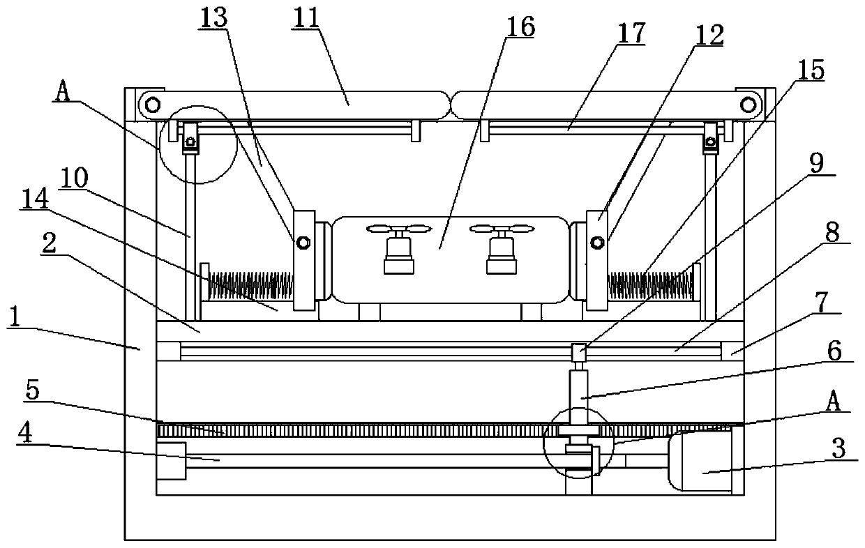
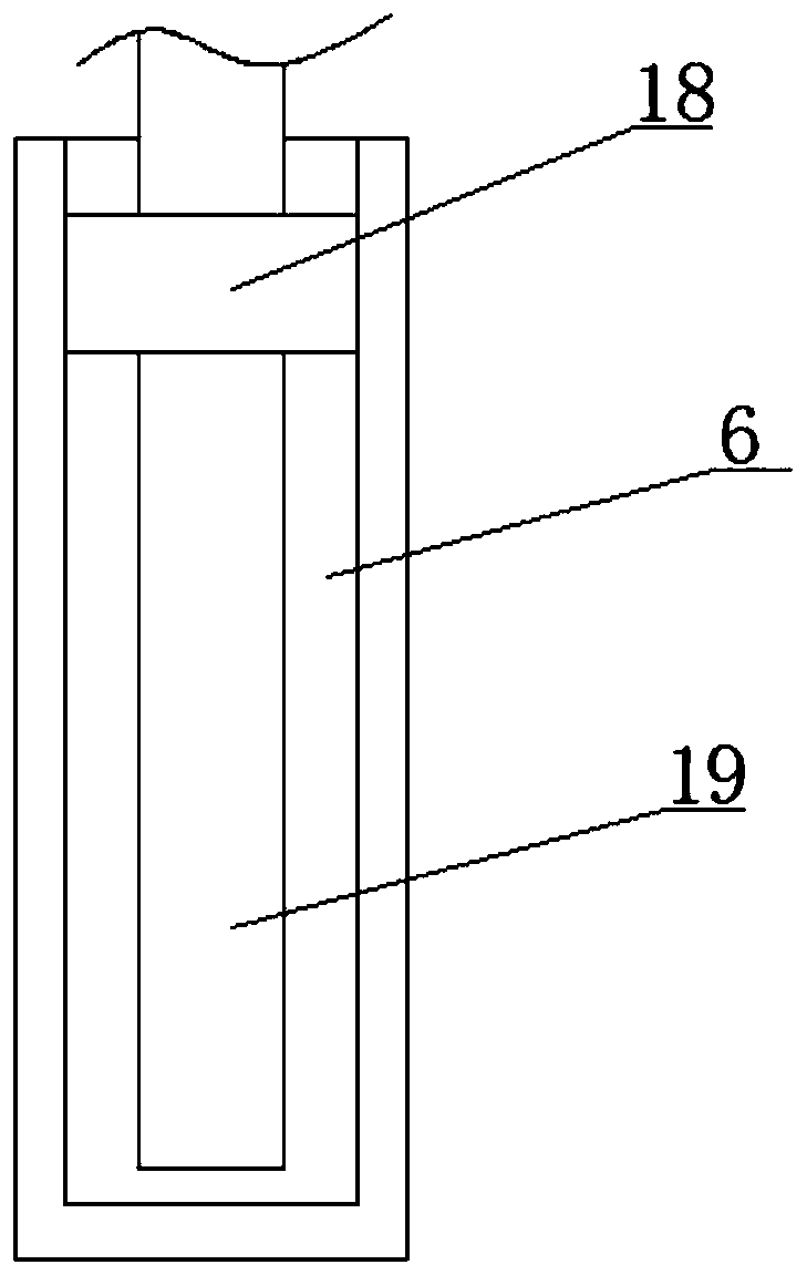
[0025] refer to Figure 1-5 In this embodiment, an unmanned aerial vehicle operation platform is proposed, including a box body 1, a lifting plate 2 is slidably connected to the inner wall of the box body 1, and a driving motor 3 is rotatably connected to the inner wall of the bottom of one side of the box body 1 to drive Screw rod 4 is fixedly installed on the output shaft of motor 3, screw rod 4 is threadedly connected with moving plate, and the top of moving plate is connected with rotating cover 6, and the inwall of rotating cover 6 is threadedly connected with screw mandrel 19, and the screw mandrel 19 The top end extends into the box body 1 and is connected with the lifting plate 2. A rack 5 is fixedly installed on the inner wall of the box body 1. A gear 20 is fixedly set on the rotating cover 6. The gear 20 meshes with the rack 5, and the lifting plate Two pull rods 10 are symmetrically fixedly installed on the top of 2, and two cover plates 11 are symmetrically connec...
Embodiment 2
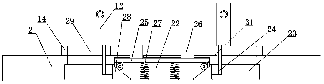
[0033]In this embodiment, the lifting plate 2 is provided with a moving chamber 22, and the inner wall of the bottom of both sides of the moving chamber 22 is provided with a moving groove 23, and the inner wall of the moving chamber 22 is slidably connected with a lifting plate 25, and the lifting plate The top four corners of the top of 25 are fixedly equipped with thimbles 26, the top of the thimble 26 extends into the box body 1, the inner wall of the moving groove 23 is slidably connected with an inclined plate 28, and one side of the inclined plate 28 extends to the moving chamber 22 The other side of the slant plate 28 is fixedly installed with a mounting rod 24, and a moving hole 29 is opened on the slide rail 14, and the top of the mounting rod 24 passes through the moving hole 29 and is fixed to the bottom of the splint 12. The connection facilitates the lifting of the UAV 2, so that the contact area between the UAV 16 and the lifting plate 2 can be reduced, and the t...
PUM
 Abstract
Description
Claims
Application Information
 - R&D
- Intellectual Property
- Life Sciences
- Materials
- Tech Scout
- Unparalleled Data Quality
- Higher Quality Content
- 60% Fewer Hallucinations
Browse by: Latest US Patents, China's latest patents, Technical Efficacy Thesaurus, Application Domain, Technology Topic, Popular Technical Reports.
© 2025 PatSnap. All rights reserved.Legal|Privacy policy|Modern Slavery Act Transparency Statement|Sitemap|About US| Contact US: help@patsnap.com