Non-contact mobile operating device and control method

A technology of moving operation and control method, applied in the direction of transportation and packaging, conveyor objects, etc., can solve the problems of object contamination, inability to drive objects to move horizontally, etc.

Active Publication Date: 2020-06-16
JIANGSU UNIV OF SCI & TECH
View PDF13 Cites 0 Cited by
  • Summary
  • Abstract
  • Description
  • Claims
  • Application Information

AI Technical Summary

Problems solved by technology

However, since there is no contact between the object and the suction cup, this method only provides vertical lifting force, but cannot drive the object to move horizontally
In order to prevent the o...

Method used


Image

  • Non-contact mobile operating device and control method
  • Non-contact mobile operating device and control method
  • Non-contact mobile operating device and control method

Examples


Embodiment Construction

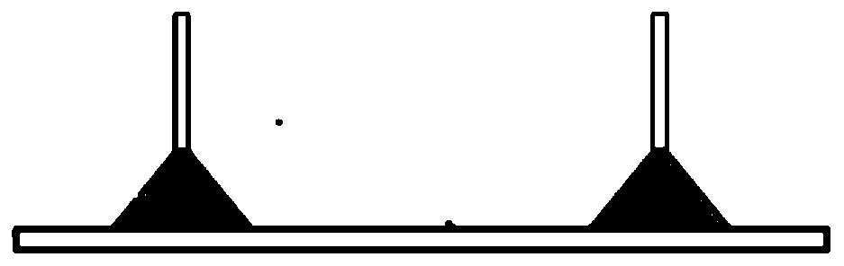
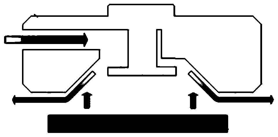
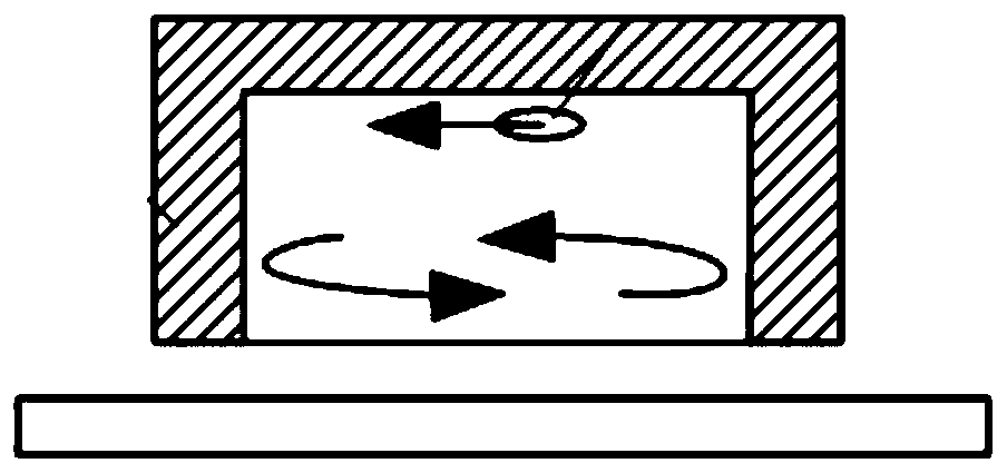
[0048] Such as Figure 1 to Figure 14 As shown, a non-contact mobile operation device of the present invention includes a circular upper plate 1, a circular lower porous medium plate 2 and a position sensor 5, the upper plate 1 is provided with a groove, and the lower porous medium plate 2 It is fixedly connected with the upper plate 1 to form a cavity, and there are four first through holes evenly arranged in the circumferential direction of the upper plate 1, and corresponding second through holes are provided at the corresponding positions of the lower porous medium plate 2, and the opposite two first through holes The hole is connected to the first vacuum pump 7, and the other two relative first through holes are connected to the second vacuum pump. The center of the upper plate 1 is provided with a third through hole, and an air inlet joint 8 is installed on the third through hole. Four brackets 3 are evenly installed on the side wall of the upper plate 1, and each bracke...


PUM


Abstract

The invention discloses a non-contact mobile operating device. The non-contact mobile operating device comprises a round upper-layer plate, a round lower-layer porous medium plate and position sensors; a groove is formed in the upper-layer plate; the lower-layer porous medium plate and the upper-layer plate are fixedly connected to form a cavity; four first through holes are evenly formed in the circumferential direction of the upper-layer plate; corresponding second through holes are formed in the corresponding positions of the lower-layer porous medium plate; the first through holes are connected with a first vacuum pump; another two opposite first through holes are connected with a second vacuum pump; a third through hole is formed in the center of the upper-layer plate; an air inlet joint is mounted on the third through hole; four supports are evenly mounted on the side wall of the upper-layer plate; a two-position three-way electromagnetic reversing valve, a position sensor and anair spraying opening are mounted on each support; the first vacuum pump and a second vacuum pump are connected with the two-position three-way electromagnetic reversing valves through pipelines; andthe two-position three-way electromagnetic reversing valves are connected with the air spraying openings. According to the device, the strength and the direction of the air flow on the surface of an object are changed through pumping of the miniature vacuum pumps, so that the object moves, and the complete non-contact effect can be realized.

Description

technical field [0001] The invention relates to a non-contact mobile operation device and a control method, and belongs to the field of non-contact mobile operation of light and thin objects. Background technique [0002] Due to the contact with the object, the traditional rubber vacuum suction cup has problems such as pollution, and it is easy to cause scratches and cracks on the surface of the object. The current popular non-contact transportation methods mostly use non-contact vacuum suction cups, including Bernoulli suction cups and swirling suction cups. Such as figure 1 As shown, using Bernoulli’s principle, where the flow rate is high and the pressure is low, the object (2) is grasped by the vacuum chuck (1) under the action of negative pressure, and the supply air flows out from the gap between the device and the object, and the device and the object are not in contact. . Such as the patent "A Simple Bernoulli Suction Cup" (publication number: CN108068136A, public...

Claims


Application Information

Patent Timeline
IPC IPC(8): B65G47/91
CPCB65G47/917
Inventor 钟伟林以恒杨锐
Owner JIANGSU UNIV OF SCI & TECH
Why Eureka
Try Eureka