Detection device for valve machining
A detection device and valve technology, which is applied in measuring devices, liquid tightness measurement using liquid/vacuum degree, fluid tightness test, etc., can solve the problem of inaccurate valve detection and achieve accuracy assurance and enhanced accuracy , the effect of improving accuracy
- Summary
- Abstract
- Description
- Claims
- Application Information
AI Technical Summary
Problems solved by technology
Method used
Image

Examples
Embodiment 1
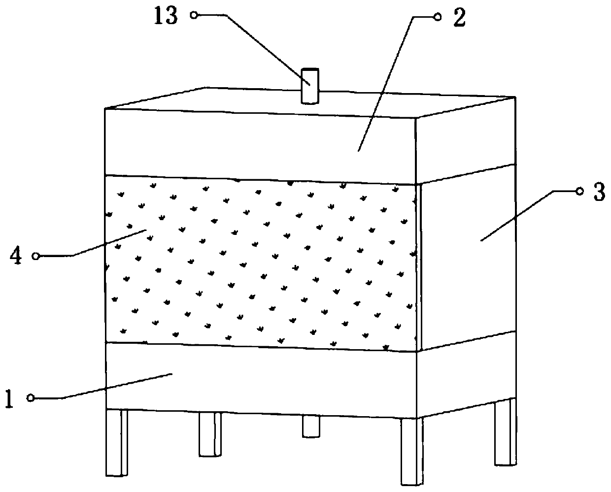
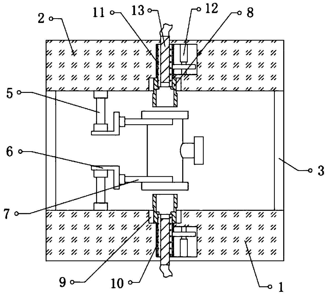
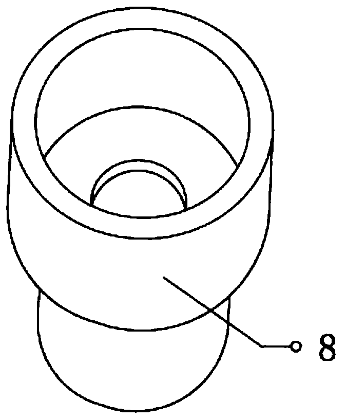
[0029] refer to Figure 1-3 , a detection device for valve processing, comprising a sealed chamber, the sealed chamber is provided with a base 1, a fixed frame 3 and a top seat 2 fixedly connected in sequence, and one end of the fixed frame 3 is provided with a sealed door 4, the top of the base 1 and the top seat 2 One side of the bottom is fixed with a cylinder 5, and one end of the cylinder 5 is fixed with a fixed frame 6, and one side of the fixed frame 6 is fixed with a horizontally arranged electric gripper 7, and the middle positions of the top of the base 1 and the bottom of the top seat 2 are uniform. A detection tube 8 is provided, and the detection tube 8 is connected with a rotating telescopic mechanism, one end of the outer wall of the detection tube 8 is adapted to the valve port, and the other end of the detection tube 8 is connected with a ventilation mechanism, and the inner wall of the sealed chamber is provided with an air pressure detector .
[0030] In th...
Embodiment 2
[0035] refer to Figure 4-5 , a detection device for valve processing, the outer wall of the detection tube 8 is detachably connected with a seal, and the top of the seal is fixed with a rubber pad 16, and the seal is set as two arc-shaped auxiliary plates 14, and the auxiliary plate 14 Both ends of the tube are fixed with fixed blocks 15, one side of the fixed block 15 is provided with a fixed hole, and the outer wall of the detection tube 8 is provided with a ring-shaped card slot 18, and the card slot 18 is compatible with the auxiliary plate 14;
[0036] The top outer wall of the rubber pad 16 is provided with a plurality of arc-shaped grooves 17, and the grooves 17 are arranged at intervals.
[0037] When in use, after the detection tube 8 is screwed into the valve port, the rubber pad 16 on the auxiliary plate 14 is pressed against the valve port, and the arc-shaped groove 17 is used to improve the sealing performance of the valve port to ensure the accuracy of the air t...
PUM
 Abstract
Description
Claims
Application Information