Eureka AIR delivers breakthrough ideas for toughest innovation challenges, trusted by R&D personnel around the world.

Signal integral deviation removing method and system and electronic device

A signal integration and deviation technology, applied in the field of signal processing, can solve problems such as large demand for computing resources, cumulative amplification of the DC component of the signal, and inability to eliminate system errors, so as to reduce the demand for computing resources, eliminate the cumulative deviation of integration, and reduce signal noise. Effect

Active Publication Date: 2020-06-16
GUANGZHOU AUTOMOBILE GROUP CO LTD
View PDF7 Cites 1 Cited by
  • Summary
  • Abstract
  • Description
  • Claims
  • Application Information

AI Technical Summary

Problems solved by technology

[0002] In the field of engineering, there are many parameters that cannot be obtained directly. It is necessary to integrate the directly obtained signals to obtain the desired parameters. However, the integration will cause the DC component of the original signal to accumulate and amplify. Therefore, signal integration and debiasing processing are required.
A variety of integral debiasing methods have been developed in this field, but there are shortcomings such as insufficient real-time performance, large demand for computing resources, and limited system adaptability.
E.g figure 1 The signal integration debiasing method shown in this method takes the actual acceleration as 0 as an example. The original signal has systematic errors and fluctuations. After filtering and debiasing, the fluctuations are reduced, but the systematic errors cannot be eliminated. After the integral operation, it becomes a first-order Deviation, after filtering to remove the deviation, the deviation growth rate becomes slower, but there is still a first-order deviation

Method used


Image

  • Signal integral deviation removing method and system and electronic device
  • Signal integral deviation removing method and system and electronic device
  • Signal integral deviation removing method and system and electronic device

Examples


Embodiment Construction

[0045] Various exemplary embodiments, features, and aspects of the present disclosure will be described in detail below with reference to the accompanying drawings. The same reference numbers in the figures indicate functionally identical or similar elements. While various aspects of the embodiments are shown in drawings, the drawings are not necessarily drawn to scale unless specifically indicated.

[0046] In addition, in order to better illustrate the present invention, numerous specific details are given in the following specific examples. It will be understood by those skilled in the art that the present invention may be practiced without certain of the specific details. In some instances, means, elements and circuits well known to those skilled in the art have not been described in detail so as to highlight the gist of the present invention.

[0047] Such as figure 1 Shown is a flow chart of a signal integration debiasing method in the prior art.

[0048] Such as f...


PUM


Abstract

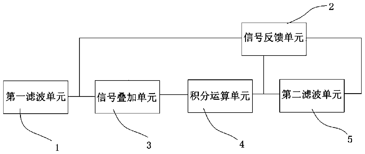
The invention provides a signal integral deviation removing method and system and an electronic device. The method comprises the following steps: receiving an acceleration characteristic signal, and performing filtering deviation removing processing on the acceleration characteristic signal to obtain a filtered deviation-removed acceleration signal; receiving a speed characteristic signal deviation feedback calculated amount in real time; superposing the filtered and deviated acceleration characteristic signal and the speed characteristic signal deviation feedback calculated amount to obtain asuperposed signal; performing integral operation on the superposed signal to obtain a first speed characteristic signal; and carrying out filtering and deviation removing processing on the first speed characteristic signal to obtain a second speed characteristic signal. The system is used for executing the method, and a computer program is stored in the electronic device to execute the method. Byimplementing the method, the real-time performance and the system application range can be improved, and the operation resource requirement is reduced.

Description

technical field [0001] The invention relates to the technical field of signal processing, in particular to a method for signal integration and debiasing, a system thereof, and electronic equipment. Background technique [0002] In the field of engineering, there are many parameters that cannot be obtained directly. It is necessary to integrate the directly obtained signals to obtain the desired parameters. However, the integration will cause the DC component of the original signal to accumulate and amplify. Therefore, signal integration and debiasing processing are required. In this field, a variety of integral debiasing methods have been developed, but there are shortcomings such as insufficient real-time performance, large demand for computing resources, and limited system adaptability. For example figure 1 The signal integration debiasing method shown in this method takes the actual acceleration as 0 as an example. The original signal has systematic errors and fluctuatio...

Claims


Application Information

Patent Timeline
Patent Type & Authority Applications(China)
IPC IPC(8): H03H17/02
CPCH03H17/0201
Inventor 邱昱王祥
Owner GUANGZHOU AUTOMOBILE GROUP CO LTD
Why Eureka
Eureka Blog
Learn More