Photoacoustic image generation apparatus, signal processing device, and photoacoustic image generation method

Active Publication Date: 2017-03-16
FUJIFILM CORP
View PDF11 Cites 21 Cited by
  • Summary
  • Abstract
  • Description
  • Claims
  • Application Information

AI Technical Summary

Benefits of technology

The present invention provides a photoacoustic image generation apparatus, a signal processing device, and a photoacoustic image generation method that can improve the image quality of a photoacoustic image without reducing the number of photoacoustic images generated per unit time. This is achieved by averaging a plurality of pieces of measurement data and performing noise reduction filtering processing on the photoacoustic image. Additionally, the apparatus can detect the position of the generation source of the photoacoustic wave from the photoacoustic image after performing the noise reduction filtering processing. This improves the accuracy of the image and allows for better visualization of the insertion needle during medical procedures.

Problems solved by technology

In the case of generating photoacoustic waves in the insertion needle, when the insertion needle is inserted to a deep position, it is not possible to detect the photoacoustic waves with sufficient intensity by the ultrasound probe placed on the body surface.
The above problem is not limited to the insertion needle, and can also occur in the case of trying to check the positions of other inserts inserted into the subject, such as a catheter or a guide wire, using photoacoustic waves generated in these inserts.

Method used


Image

  • Photoacoustic image generation apparatus, signal processing device, and photoacoustic image generation method
  • Photoacoustic image generation apparatus, signal processing device, and photoacoustic image generation method
  • Photoacoustic image generation apparatus, signal processing device, and photoacoustic image generation method

Examples


Embodiment Construction

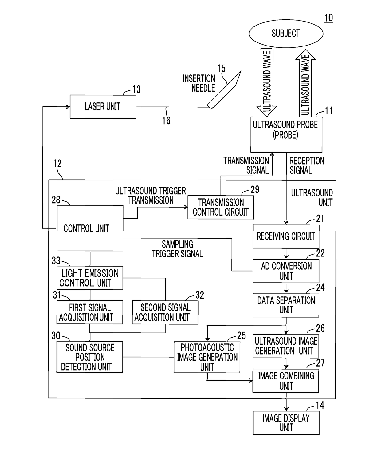
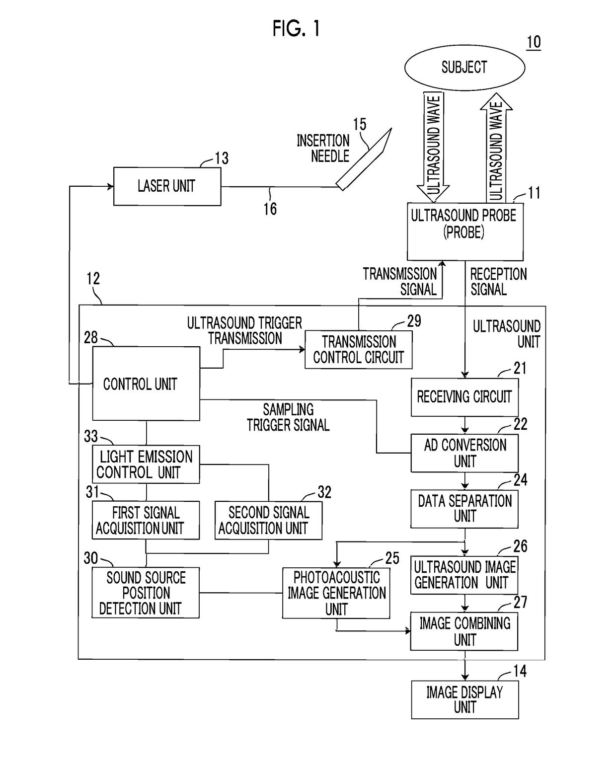
[0048]Hereinafter, embodiments of the present invention will be described in detail with reference to the diagrams. FIG. 1 shows a photoacoustic image generation apparatus according to an embodiment of the present invention. A photoacoustic image generation apparatus 10 includes a probe (ultrasound probe) 11, an ultrasound unit 12, a laser unit 13, and an insertion needle 15. In the embodiment of the present invention, an ultrasound wave is used as a photoacoustic wave. However, the present invention is not limited to the ultrasound wave, and an acoustic wave having an audible frequency may be used as long as an appropriate frequency can be selected according to an examination target, measurement conditions, or the like.

[0049]The laser unit 13 that is a light source is configured as a laser diode light source (semiconductor laser light source), for example. Types of light sources are not particularly limited, and the laser unit 13 may be an optical amplification type laser light sou...


PUM


Abstract

An insertion needle 15 has a photoacoustic wave generating portion that generates a photoacoustic wave by absorbing light emitted from a laser unit 13. A photoacoustic image generation unit 25 generates a photoacoustic image based on the detection signal of the photoacoustic wave emitted from the insertion needle 15. The sound source position detection unit 30 detects the photoacoustic wave generating source from the photoacoustic image. A first signal acquisition unit 31 acquires an S value, and a second signal acquisition unit 32 acquires an N value. A light emission control unit 33 controls the number of light emissions and the light emission interval of the laser unit 13 for one photoacoustic image generation based on the ratio between the S value and the N value. The photoacoustic image generation unit 25 generates a photoacoustic image by at least adding the detection signals of photoacoustic waves corresponding to the number of light emissions.

Description

CROSS-REFERENCE TO RELATED APPLICATIONS[0001]This application is a Continuation of PCT International Application No. PCT / JP2015 / 056792 filed on Mar. 9, 2015, which claims priority under 35 U.S.C. §119 (a) to Japanese Patent Application No. 2014-134044 filed on Jun. 30, 2014. Each of the above application(s) is hereby expressly incorporated by reference, in its entirety, into the present application.BACKGROUND OF THE INVENTION[0002]1. Field of the Invention[0003]The present invention relates to a photoacoustic image generation apparatus, a signal processing device, and a photoacoustic image generation method, more specifically, to a photoacoustic image generation apparatus, a signal processing device, and a photoacoustic image generation method for generating a photoacoustic image by detecting photoacoustic waves generated in a subject after emitting light to the subject.[0004]2. Description of the Related Art[0005]As a kind of image examination method capable of examining the state ...

Claims


Application Information

Patent Timeline
IPC IPC(8): A61B5/00A61B1/00A61B8/12A61B1/07
CPCA61B5/0095A61B1/07A61B2017/3413A61B8/12A61B2576/00A61B1/00006A61B17/3403A61B8/08A61B8/4416A61B5/6848A61B5/061
Inventor IRISAWA, KAKU
Owner FUJIFILM CORP
Why Eureka
Try Eureka