[0012]A
sensor system for determining at least one flow property of a fluid medium flowing in a main flow direction is therefore proposed, via which the disadvantages of known methods and strategies may be at least largely avoided, and in which a velocity field, in particular on the sensor chip side of the sensor carrier, which has long-term stability, in particular with regard to the
particle contamination, may be generated.
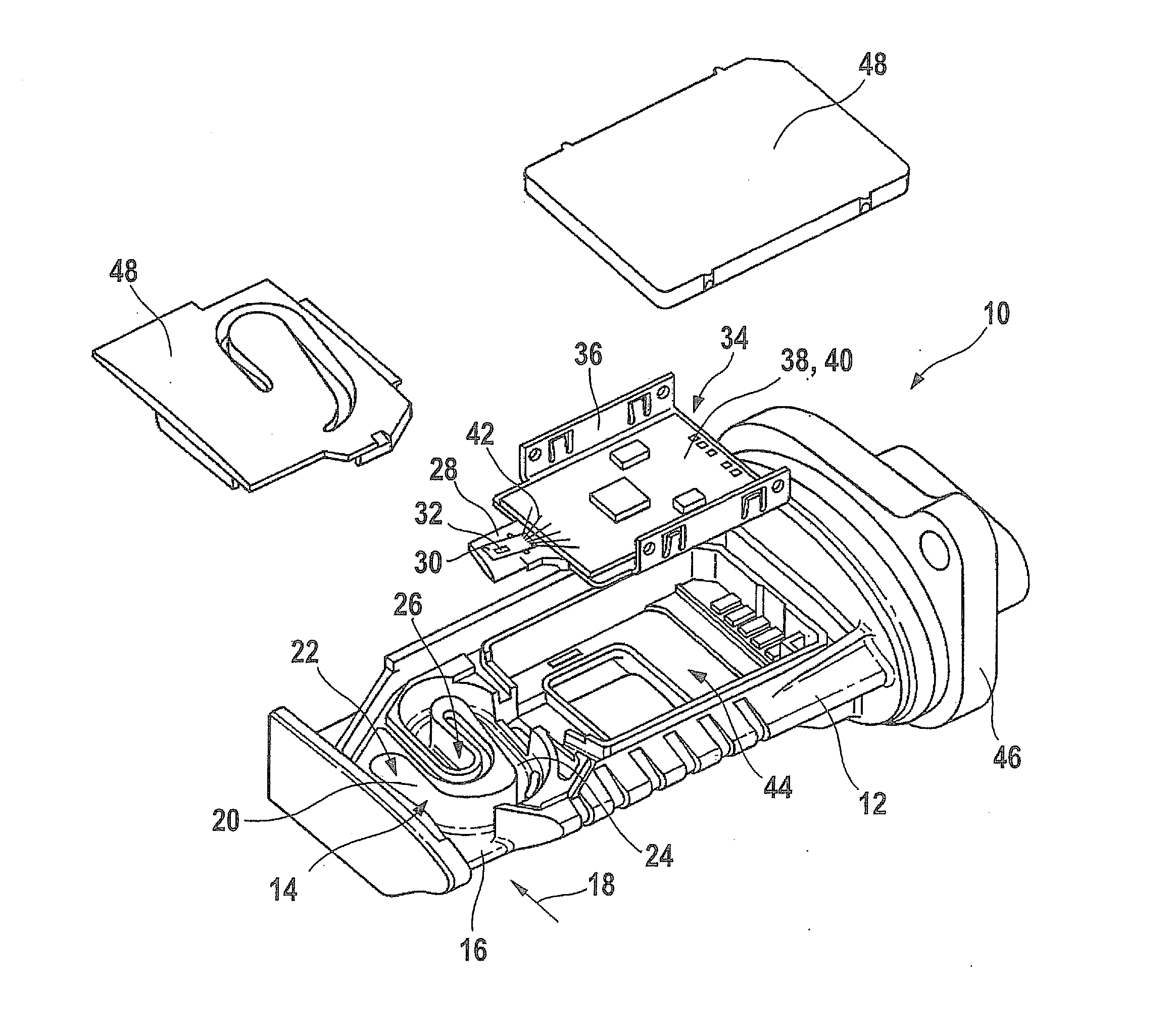
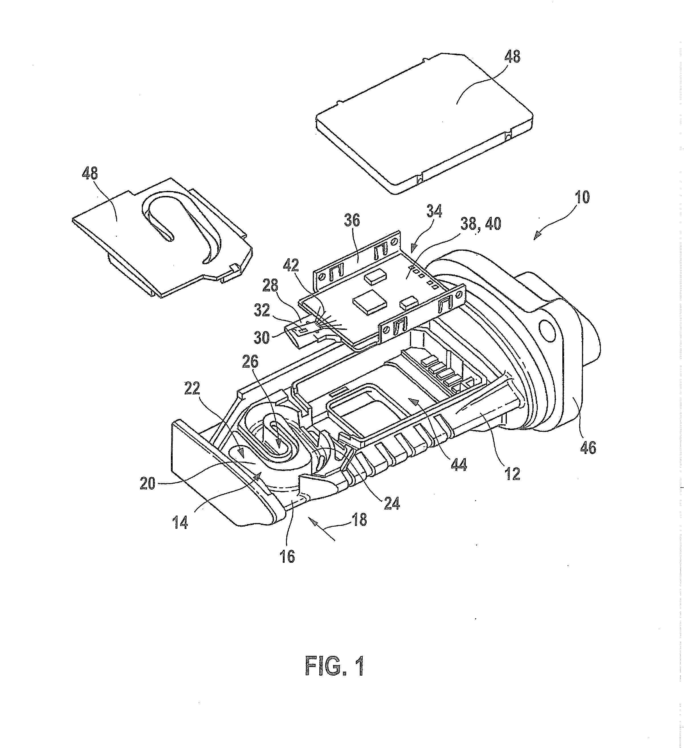
[0023]In this way, the electronic module of the sensor
system may be greatly simplified, and a base plate and a separate sensor carrier, for example, may be dispensed with. The base plate and sensor carrier may be replaced by a single
printed circuit board on which, for example, a control and evaluation circuit of the sensor
system may also be completely or partially situated. This control and evaluation circuit of the sensor
system is used to control the at least one sensor chip and / or the evaluation of the signals generated by this sensor chip. Thus, by combining the mentioned elements, the complexity of manufacturing the sensor system may be significantly reduced, and the space requirement for the electronic module may be greatly reduced.
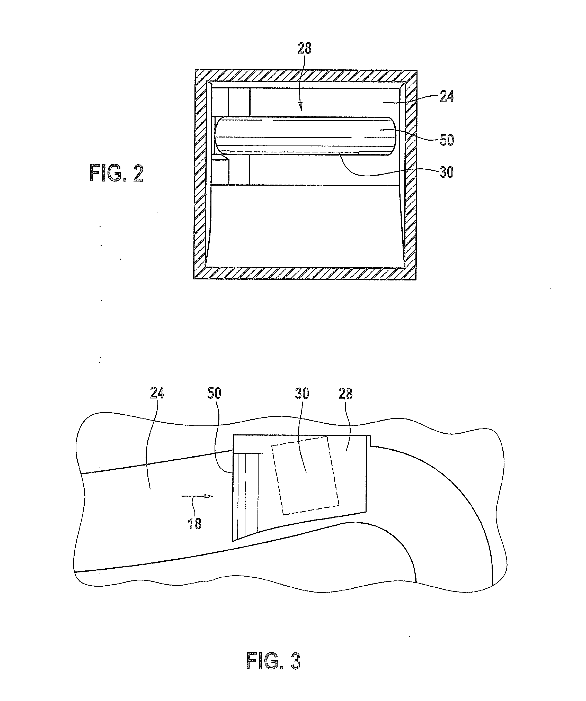
[0027]The sensor chip may be electrically contacted via at least one
electrical connection. For example, the sensor carrier, in particular a
printed circuit board which forms the sensor carrier or an extension of this
printed circuit board, may have one or multiple printed conductors and / or contact pads which are connected to corresponding contacts on the sensor chip, for example with the aid of a
bonding process. In this case, the
electrical connection may be protected by at least one cover and be separated from the fluid medium. This cover may in particular be designed as a so-called “glob top,” for example as plastic drops and / or
adhesive drops, which covers the
electrical connection, for example the bond wires. In particular, influences on the flow by the electrical connection may also be avoided in this way, since the glob top has a
smooth surface. In addition, the sensor chip may have at least one sensor area. This sensor area may be, for example, a sensor surface made, for example, of a porous
ceramic material, and / or in particular may be a sensor diaphragm.
[0028]With the aid of the present invention, changes in the velocity field may be reduced compared to a new or initial state of the sensor system; in particular, however, regions of low velocity in the particle gathering area of the sensor area may be avoided or reduced. Over the service life of the sensor system, such low-velocity regions may be used as a collection point for increasingly larger numbers of particles. Since the particles change the tendency toward
contamination and the
heat transfer to the air, the following effects in particular are achieved by individual measures or by a combination of measures. The growth of the boundary layer due to contamination is avoided or at least reduced, since an effective reduction in the
flow pulse in the vicinity of the sensor area is thus achieved. The vortex foci, specks of dust, or collection points which form in the region around the sensor area are avoided or at least reduced. Separations on the side of the sensor carrier facing the sensor chip as well as on the side of the sensor carrier facing away from the sensor chip are avoided or at least reduced. In addition, the aim is to avoid or at least reduce low-velocity regions which result from other causes. Furthermore, the measures are also suitable for nonstationary reverse flow states, i.e., pulsation in the intake tract. Via appropriate designs at the front and / or rear edge of the sensor carrier, the aim ideally is to adapt the bandwidths of the velocity fields to one another during the forward and reverse flow. As a
side effect, the stabilizing measures result in smaller velocity fluctuations for the instantaneously measured mean value in the region of the sensor area, resulting in lower
signal noise and better reproducibility.
[0029]With the aid of the present invention, for reducing the tendency toward
particle contamination, secondary velocities may be generated or induced in the main flow, and / or low-velocity regions may be avoided on and in the immediate proximity of the sensor area, in particular of the micromechanical sensor diaphragm.
[0030]In addition, a topologically more exact definition of the flow field, including the boundary layer flow in the immediate proximity of the sensor area, in particular of the sensor diaphragm, is possible, i.e., avoidance of characteristics of the flow-defining structures, which change with the mass flow or flow states, such as, for example, stagnation points and
saddle points, separation lines, vortex foci, variation of the
wall shear stress over time, and the like. The avoidance of or reduction in the particle accumulation as well as the
harmonization of the flow over the sensor area are achieved by the measures according to the present invention.

