
Image data interpolation method and device, storage medium and terminal

An image data and interpolation method technology, applied in the field of image processing, can solve the problems of large differences in data pixels and blurred screens, and achieve the effects of improving performance, improving resolution, and improving interpolation accuracy.

Active Publication Date: 2020-06-16
SPREADTRUM COMM (SHANGHAI) CO LTD
View PDF6 Cites 2 Cited by
  • Summary
  • Abstract
  • Description
  • Claims
  • Application Information

AI Technical Summary

Problems solved by technology

Frame loss may cause a large difference in pixels between two adjacent fields of data, and the use of time-domain interpolation may cause blurred screens

Method used


Image

  • Image data interpolation method and device, storage medium and terminal
  • Image data interpolation method and device, storage medium and terminal
  • Image data interpolation method and device, storage medium and terminal

Examples


Embodiment Construction

[0035] As mentioned in the background art, the de-interleaving algorithm in the prior art has defects and needs to be further improved.

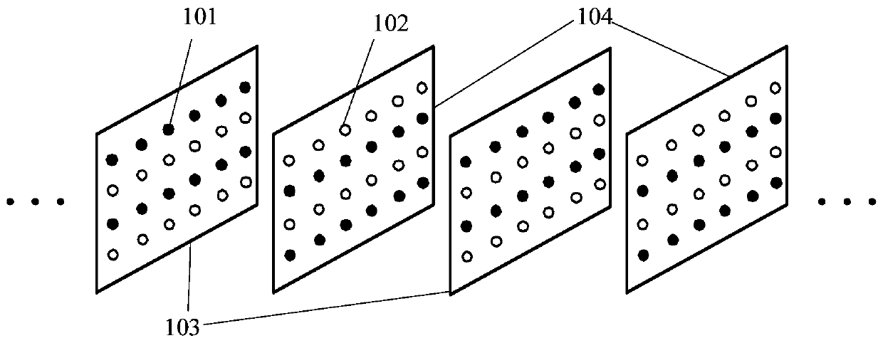
[0036] In order to reduce the bandwidth, the current TV system usually adopts interlaced scanning technology. The data generated by each scan is a field, which is respectively called an odd field (also called a top field) or an even field (also called a bottom field). figure 1 It shows a data stream obtained by an interlaced scanning technique in the prior art solution. Such as figure 1 As shown, the black solid dots 101 represent known pixel points obtained by interlaced scanning, and the hollow dots 102 represent missing points, which may also be referred to as points to be interpolated. Wherein, odd field 103 refers to a field containing only odd rows of known pixels, and even field 104 refers to a field containing only even rows.

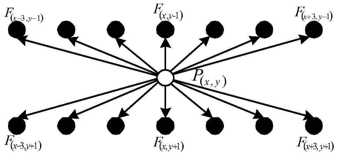
[0037] figure 2 It is a schematic diagram of a boundary direction-based spatial interpolation method i...


PUM


Abstract

The invention discloses an image data interpolation method and device, a storage medium and a terminal, and the method comprises the steps: carrying out the interlaced scanning of input image data, soas to obtain a plurality of fields arranged according to a time sequence, and each field comprising a plurality of to-be-interpolated points and a plurality of pixel points; for the current to-be-interpolated point in each field, calculating by adopting a time domain interpolation method to obtain a predicted pixel value of the current to-be-interpolated point; determining a pixel value of a first pixel point adjacent to the current to-be-interpolated point, the horizontal coordinate of the first pixel point being the same as the horizontal coordinate of the current to-be-interpolated point,and the first pixel point and the current to-be-interpolated point being located in the same field; at least performing difference detection on the predicted pixel value of the current to-be-interpolated point and the pixel value of the first pixel point to obtain a difference detection result; and when the difference detection result exceeds a first preset threshold, determining the pixel value of the current to-be-interpolated point by adopting a spatial interpolation method. According to the technical scheme provided by the invention, the interpolation accuracy can be improved, and the performance of the de-interleaving algorithm is improved.

Description

technical field [0001] The present invention relates to the technical field of image processing, in particular to an image data interpolation method and device, a storage medium, and a terminal. Background technique [0002] At present, most television systems and digital video disc (Digital Video Disk, DVD for short) playback devices adopt the interlaced scanning technology. The use of interlaced scanning can effectively save the bandwidth required for transmission, but at the same time, it will cause flickering between lines, flickering between fields, and sawtooth effects during the display process, which seriously affects the sensory experience of users. In order to improve user experience, the de-interlace algorithm is widely used as a video post-processing link. The de-interlacing algorithm can fill in pixel values ​​of missing points (also referred to as points to be interpolated) introduced by interlaced scanning through prediction, thereby improving the display eff...

Claims


Application Information

Patent Timeline
Patent Type & Authority Applications(China)
IPC IPC(8): H04N7/01H04N19/587H04N19/59
CPCH04N7/0135H04N19/587H04N19/59
Inventor 孙振燕罗小伟李荣林福辉
Owner SPREADTRUM COMM (SHANGHAI) CO LTD
Learn More