Magnetic medium assisted plate punching forming device and method

A magnetic medium and plate technology, applied in the field of plate blanking, can solve the problems of unbalanced force on the punch, poor cross-section quality, and excessive burr, so as to enhance the ability to resist deformation, eliminate the gap problem, and make a tight arrangement. Effect

Active Publication Date: 2020-06-19
HARBIN UNIV OF SCI & TECH
View PDF16 Cites 8 Cited by
  • Summary
  • Abstract
  • Description
  • Claims
  • Application Information

AI Technical Summary

Problems solved by technology

[0007] The purpose of this invention is to solve a series of problems such as scratches, warping deformation, excessive burrs, p

Method used


Image

  • Magnetic medium assisted plate punching forming device and method
  • Magnetic medium assisted plate punching forming device and method
  • Magnetic medium assisted plate punching forming device and method

Examples


specific Embodiment approach 1

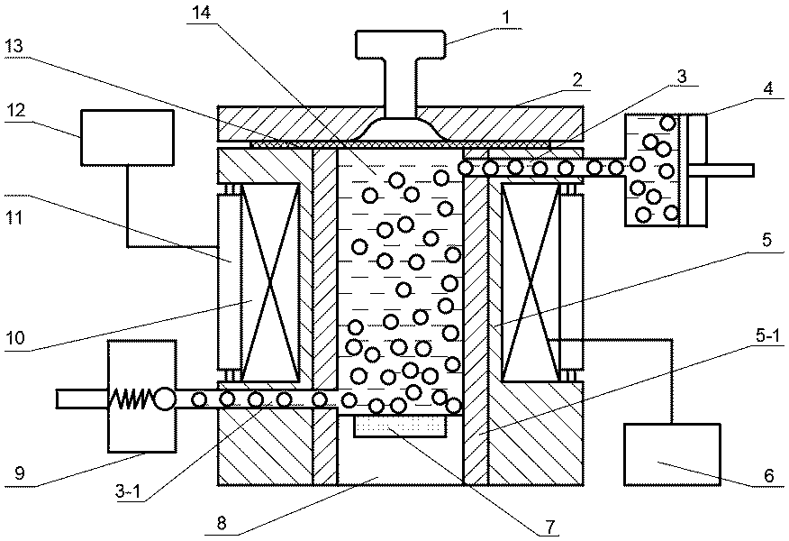
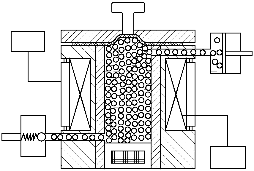
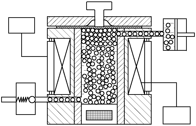
[0024] Specific implementation mode one: combine figure 1 Describe this embodiment, this embodiment includes a punch 1, a blank holder 2, a liquid channel input end 3, a liquid channel output end 3-1, a plunger cylinder 4, a die 5, a liquid storage chamber 5-1, a magnetic control Unit 6, pressure sensor 7, sealing block 8, pressure relief valve 9, coil 10, cooling device 11, cooling control unit 12, slab 13, magnetic medium 14. Firstly, the plunger cylinder 4 injects magnetic media 14 with different particle volume fractions, in which the base liquid accounts for 10%-35%, the magnetizable particles account for 40%-80%, and the stabilizer accounts for 1-5%. The slab 13 is placed on the upper end surface of the die 5, the blank holder 2 and the die 5 are aligned up and down, a part of the space is left in the blank holder 2, and guide holes are set, and the punch 1 and the blank holder 2 fit in a small gap . The coil 10 is embedded in the die 5 , and is controlled by the magne...

specific Embodiment approach 2

[0025] Specific implementation mode two: combination figure 1 To illustrate this embodiment, this embodiment is the injection of magnetic media with different particle volume fractions from the plunger cylinder in Step 1, wherein the base liquid accounts for 45%, the magnetized particles account for 50%, and the stabilizer accounts for 5%. Other steps are the same as in the first embodiment.

specific Embodiment approach 3

[0026] Specific implementation mode three: combination figure 1 This embodiment is described. In the first step, the plunger cylinder injects magnetic media with different particle volume fractions, wherein the base liquid accounts for 24%, the magnetized particles account for 70%, and the stabilizer accounts for 6%. Other steps are the same as in the first embodiment.


PUM

PropertyMeasurementUnit
The inside diameter ofaaaaaaaaaa

Abstract

The invention provides a magnetic medium assisted plate punching forming device and method, and relates to a plate flexible medium assisted punching forming device and method. The magnetic medium assisted plate punching forming device and method are used for solving a series of problems that during traditional plate punching forming, scratches, buckling deformation, too large burrs, poor fracturesurface quality and tipping caused by imbalanced force bearing of a punch are easily generated. According to the device, a coil 10 is embedded into a female die 5 and connected with a magnetic controlunit 6, a pressure sensor 7 is arranged in a sealing block 8, a magnetic medium 14 is injected into a cavity defined by the sealing block, a liquid storage chamber 5-1 and a plate blank 13, and the arrangement state and the rheological property of the magnetic medium are adjusted through the magnetic control unit 6. According to the method, the magnetic medium 14 with different particle volume fractions is injected into the liquid storage chamber 5-1 of the female die 5 through a plunger cylinder 4, different backpressure force transmission effects are achieved for the plate blank 13 in the punching process under adjustment and control of the magnetic control unit 6, the force bearing state and the deformation behavior around a plate punching region are changed, and improvement of the quality of punching parts is promoted. The method can quantitatively adjust and control the effect of a force transmission medium according to the actual working condition requirements, and the device and the method are suitable for punching forming of high-quality metal plates.

Description

technical field [0001] The invention relates to a plate blanking process method, in particular to a magnetic medium-assisted plate blanking forming device and method, and belongs to the technical field of plate blanking. Background technique [0002] Punching is a sheet forming process that uses a die to separate parts or blanks of the required shape and size from the sheet (pipe) material, and it accounts for the largest proportion in stamping production. Except for the metal material near the shear contour line, the sheet itself does not produce plastic deformation. However, there are many deficiencies in the ordinary blanking process. First, due to the uneven thickness and material of the plate (pipe), the punch is subject to a large lateral force, which is prone to breakage and chipping; secondly, due to the There is a gap between them, so that the action force and reaction force of the convex and concave dies on the sheet are not on the same straight line, thus generat...

Claims


Application Information

Patent Timeline
IPC IPC(8): B21D26/14B21D28/02
CPCB21D26/14B21D28/02
Inventor 李峰柳振宇牟媛媛
Owner HARBIN UNIV OF SCI & TECH
Why Eureka
Try Eureka