Closed-cycle hydro-jet thruster

a closed-cycle, thruster technology, applied in the direction of clutches, transmissions, fluid couplings, etc., can solve the problems of reducing the torque-to-thrust conversion ratio provided by the direct torque-to-thrust conversion mechanism, limiting the use of land vehicles for hovercrafts, and hindering the efficient generation of thrust force to drive land, sea and air vehicles. , to achieve the effect of reducing the development of vortices, reducing the overall performance of blades

Inactive Publication Date: 2013-11-14
MARCUS ESSAM TAWFIK
View PDF5 Cites 4 Cited by
  • Summary
  • Abstract
  • Description
  • Claims
  • Application Information

AI Technical Summary

Benefits of technology

[0008]The present invention also provides a CCHJT that can be used for propelling all types of land, sea and air vehicles, and which enables providing high Power-to-Thrust conversion ratios regardless of the cruising speed of the propelled vehicle.
[0019]In a preferred embodiment, each of the said blades of the rotor has a beak-like leading edge when viewed in cross-sectional profile, to disrupt the eddies formed due to the interaction between successive blades during operation. In another preferred embodiment, each of the said blades of the rotor has a downstream curved trailing edge when viewed in cross-sectional profile, to increase the hydrostatic pressure of the working fluid downstream the blades during operation and improve the blade's overall performance.
[0020]In a preferred embodiment, the said rotor further includes a circumferential, cylinder-shaped shroud positioned around the outer edges of the said rotor blades and has an inner surface and an outer surface, with the inner surface of the said shroud being attached to the outer edges of the said rotor blades to minimize / prevent the development of vortices around the outer edges of the blades during operation.
[0023]To increase the Thrust / Lift-to-weight ratio of the CCHJT during operation, the CCHJT rotor blades are operate at relatively high operating speeds, at which cavitations are expected to form on the upstream suction surfaces of the blades. To enable operating the blades at relatively high operating speeds without the formation of cavitations on the upstream suction surfaces of the blades, the hydraulic fluid filling the fluid flow passages and the free spaces enclosed within the CCHJT casing is maintained during operation at a pressure level higher than ambient pressure level, aided by the before mentioned fluid pressure regulating system.
[0030]In a preferred embodiment, an even number of CCHJTs are used, with the CCHJTs being arranged in one or more pairs, and with each pair of CCHJTs being designed with counter-rotating rotors, to balance out the torque effect developed by their rotating components during operation.

Problems solved by technology

This necessitates using blades having relatively high angles of attack, or coarse pitches, which decreases the Torque-to-Thrust conversion ratios provided by these direct Torque-to-Thrust conversion mechanisms.
In addition, as these conventional direct Torque-to-Thrust conversion mechanisms utilize the surrounding fluid as their working medium, so this limits their use for propelling land vehicles to Hovercrafts and the like, which are not practical for city use due to several operational limitations, and due to their low overall Torque-to-Thrust conversion ratio.
However, applying the same principal for the efficient conversion of the torque provided by a prime mover, or a motor, into a thrust force, using a rotating cascade of blades having relatively low angles of attack and operating within an open system is not described in prior Art due to the marked drop in the efficiency of the thrust force generated by low angle of attack air / hydrofoils when operating in non-stagnant upstream working fluid conditions.
And thus, in spite of the well known high efficiency of properly designed, low angle of attack air / hydrofoils in generating lift force, yet, their use for the efficient generation of thrust force to drive land, sea and air vehicles has been hindered by the before-mentioned limiting factors.

Method used


Image

  • Closed-cycle hydro-jet thruster
  • Closed-cycle hydro-jet thruster
  • Closed-cycle hydro-jet thruster

Examples


Embodiment Construction

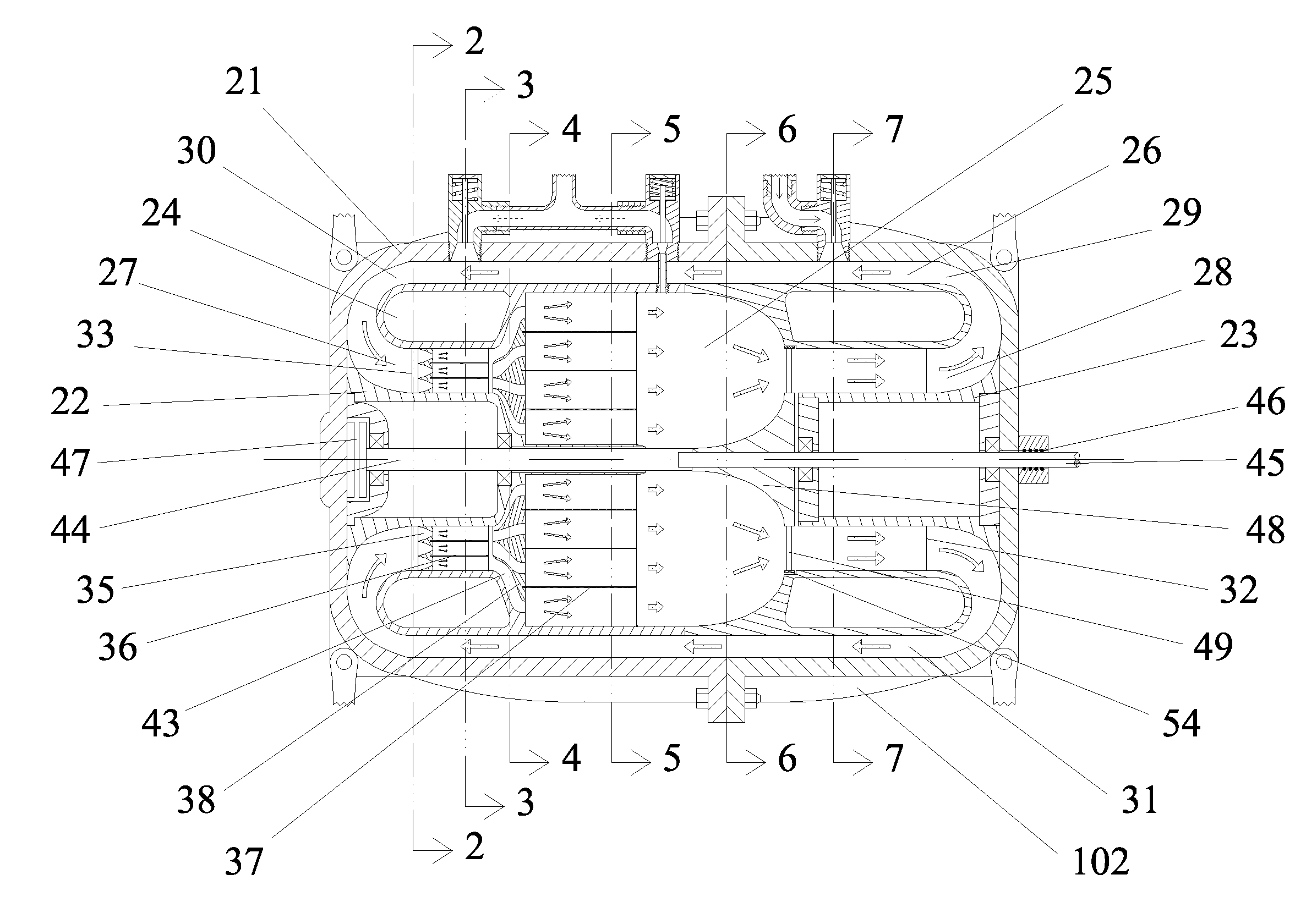
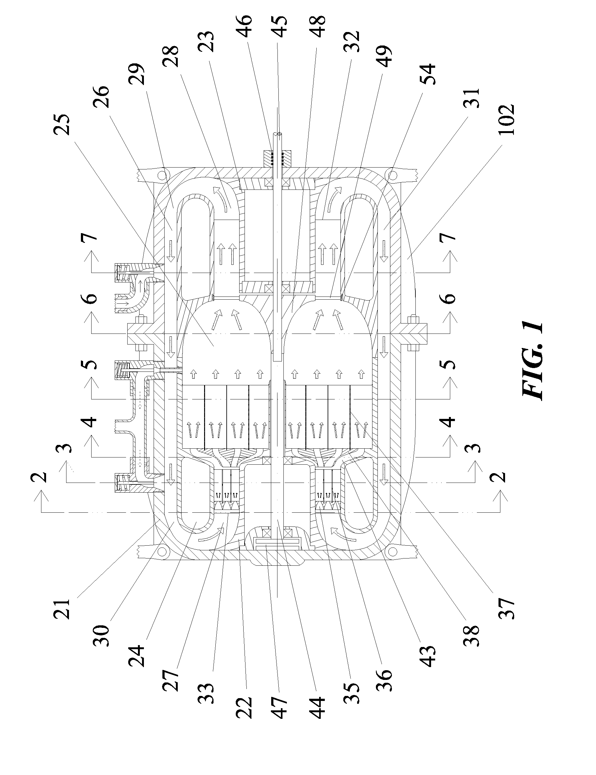
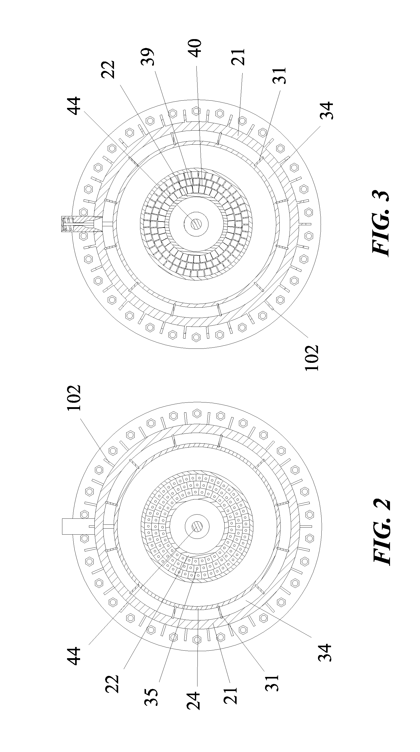
[0054]The present invention provides a closed-cycle hydro jet thruster (CCHJT) that includes a rotating cascade of blades having relatively low angles of attack, and directly interacting with a fluid medium completely enclosed within the CCHJT's casing, to generate thrust / lift force, with said generated force being used for propelling, or lifting, a movable vehicle.

[0055]The present invention also provides a CCHJT that can be used for propelling all types of land, sea and air vehicles, and which enables providing high Power-to-Thrust conversion ratios regardless of the cruising speed of the propelled vehicle.

[0056]As used hereinafter, the term “angle of attack” refers to the angle between the chord line of a blade and the vector representing the relative motion between the blade and a working fluid; and the term “low angle of attack” refers to and includes any angle of attack lying within the range between 2° and 14°.

[0057]Accordingly, the present invention provides a closed-cycle h...


PUM


Abstract

The present invention provides closed-cycle hydro jet thruster (CCHJT) used for the direct conversion of torque into thrust and / or lift force. In a preferred embodiment, the CCHJT includes an outer casing; two inner-members; an intermediate body; a plurality of convergent nozzles; a set of intersecting members; a drive shaft; a rotor assembly having a plurality of blades; a hydraulic fluid completely filling the space within the casing; and a fluid pressure regulating system. In operation, the rotating blades accelerate and compress the hydraulic fluid leading to generation of thrust / lift force on the blades, which is transmitted to the CCHJT's casing through thrust bearings. This is followed by acceleration of the working fluid within the nozzles, suddenly expanding the accelerated working fluid within sub-passages defined in-between the intersecting members, and then directing the flow of the working fluid towards the upstream suction surfaces of the blades for re-acceleration.

Description

TECHNICAL FIELD[0001]The present invention relates to a closed-cycle hydro jet thruster (CCHJT), and more particularly to a direct Torque-to-Thrust conversion device which is used for converting therein the torque provided by a prime mover, or an electric motor, into direct thrust, or lift, force, with said generated thrust, or lift, force being used directly for propelling, or lifting, a movable vehicle.BACKGROUND ART[0002]Direct Torque-to-Thrust conversion mechanisms having rotating cascades of blades that interact with a surrounding fluid medium to generate thrust / lift force are well known in the Art; with non-limiting examples of such mechanisms including aircraft and ship propellers, and open-cycle hydro jet propulsion devices. In these mechanisms, the torque provided by a prime mover or an electric motor is used in rotating a number of blades leading to acceleration of a fluid medium downstream of the blades and generation of an opposing reaction force on the rotating blades, ...

Claims


Application Information

Patent Timeline
Patent Type & Authority Applications(United States)
IPC IPC(8): F16D31/00
CPCB63H23/26
Inventor MARCUS, ESSAM TAWFIK
Owner MARCUS ESSAM TAWFIK
Why Eureka
Try Eureka