High-precision fixing device for machining

A fixing device and machining technology, applied in positioning devices, metal processing equipment, metal processing mechanical parts, etc., can solve problems such as workpiece processing effects, and achieve the effects of preventing breakage, improving clamping effect, and improving convenience.

Inactive Publication Date: 2020-06-19
王菊
View PDF7 Cites 1 Cited by
  • Summary
  • Abstract
  • Description
  • Claims
  • Application Information

AI Technical Summary

Problems solved by technology

A kind of fixing device for mechanical processing in the above-mentioned patent has the following disadvantages: when the cylindrical workpiece is fixed, the cylindrical workpiece will roll during processing, and the existing device may roll due to the rolling of the workpiece when the workpiece is processed. and affect the processing of the workpiece

Method used


Image

  • High-precision fixing device for machining
  • High-precision fixing device for machining
  • High-precision fixing device for machining

Examples


Embodiment 1

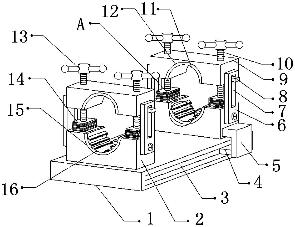
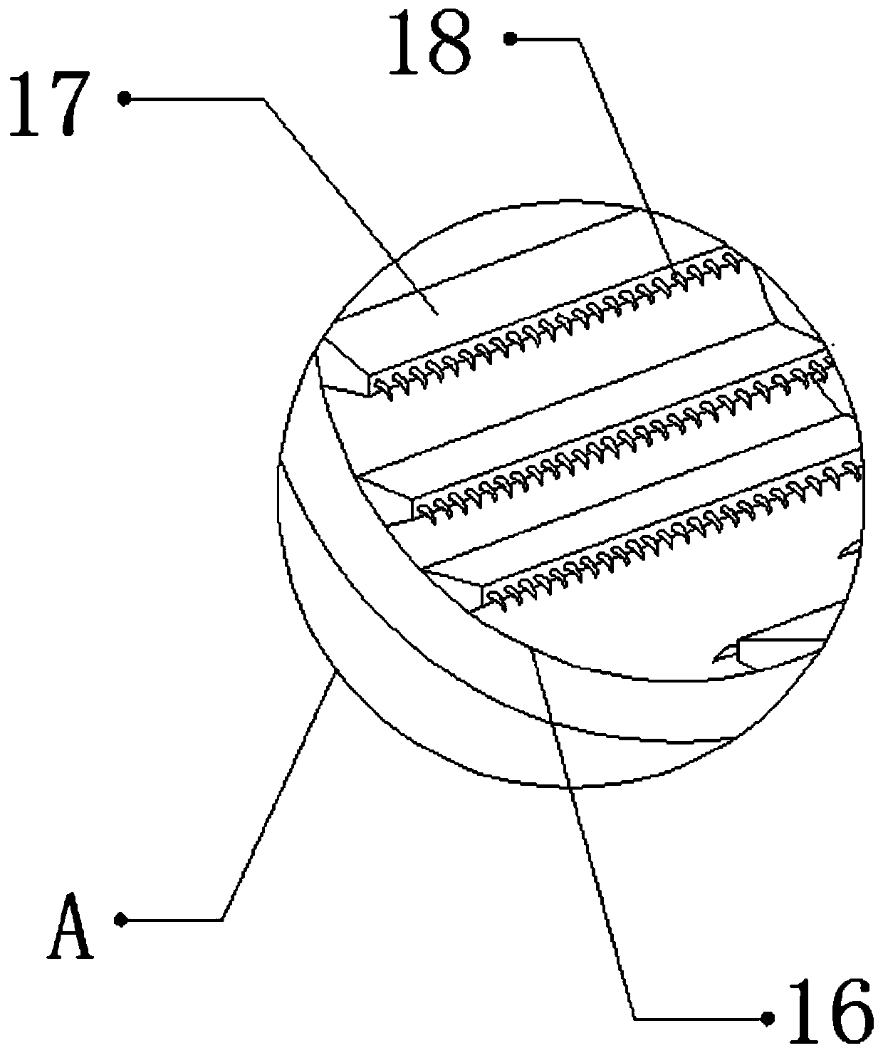
[0029] refer to Figure 1-3 , a mechanically processed high-precision fixing device, including a fixing seat 1, the outer walls of both sides of the fixing seat 1 are provided with chute 3, and the inner walls of the two chute 3 are slidably connected with sliders 4, and the two sliders 4 One side of the outer wall is connected with an L-shaped plate 5 by bolts, and one side of the outer wall of the two L-shaped plates 5 and one side of the top outer wall of the fixing seat 1 are all connected with a support seat 2 by bolts, and the tops of the two support seats 2 The outer walls are all provided with second fixing grooves 15, and the inner walls of the two second fixing grooves 15 are bonded with second protective pads 16, and the inner walls of the second protective pads 16 are provided with a plurality of ribs 17, and the ribs 17 One side outer wall is provided with a plurality of fixed teeth 18, and both sides of the top outer walls of the two support bases 2 are provided ...

Embodiment 2

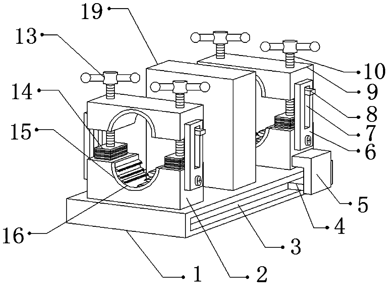
[0037] refer to Figure 4, a mechanically processed high-precision fixing device. Compared with Embodiment 1, in this embodiment, the top outer wall of the fixing seat 1 is connected with a support plate 19 by bolts near the middle position, and one side of the outer wall of the support plate 19 is provided with a through opening. 20. The outer walls on both sides and the top of the support plate 19 are provided with second threaded holes, and the inner walls of the second threaded holes are threaded with second threaded rods 21, and the top outer walls of the second threaded rods 21 are connected with the second threaded rods 21 by bolts. The second turning handle 22, and the outer wall of the second turning handle 22 is sleeved with a protective sleeve, which can fix the middle part of the workpiece so as to support the workpiece and prevent the workpiece from breaking due to a large force during processing. The workpiece can be further fixed by the second threaded rod 21 . ...


PUM


Abstract

The invention discloses a high-precision fixing device for machining. The high-precision fixing device for machining comprises a fixing base, wherein sliding grooves are formed in the outer walls of the two sides of the fixing base; sliding blocks are slidably connected to the inner walls of the two sliding grooves; L-shaped plates are fixedly connected to the outer walls of one sides of the two sliding blocks; supporting seats are fixedly connected to the outer walls of one sides of the two L-shaped plates and one side of the top outer wall of the fixing base; second fixing grooves are formedin the top outer walls of the two supporting seats; second protective pads are bonded to the inner walls of the two second fixing grooves; a plurality of ribs are arranged on the inner wall of each second protective pad correspondingly; and a plurality of fixing teeth are arranged on the outer wall of one side of each rib correspondingly. When the high-precision fixing device for machining works,a workpiece can be prevented from rolling due to acting force so that the machining deviation of the workpiece can be avoided, the offsetting between clamping plates and the supporting seats due to shaking of the clamping plates when the clamping plates move is avoided, the influence on fixing of the workpiece due to the fact that the workpiece is too short or too long is eliminated, and thus theworking convenience of the device is improved.

Description

technical field [0001] The invention relates to the technical field of machining, in particular to a high-precision fixing device for machining. Background technique [0002] Machining refers to the process of changing the shape or performance of a workpiece through a mechanical device. According to the difference in processing methods, it can be divided into cutting processing and pressure processing. During machining, the workpiece needs to be fixed by a fixing device. . [0003] After searching, the Chinese patent authorization number is CN209319615U patent, which discloses a kind of fixing device for mechanical processing, including a device main body, a first cylinder and a second cylinder are respectively arranged on both sides of the inside of the device main body, and the first cylinder The output end of the output end is connected with the first piston rod. The fixing device for this kind of machining is provided with a slot, a block, a connecting plate and a groov...

Claims


Application Information

Patent Timeline
IPC IPC(8): B23Q3/06
CPCB23Q3/062
Inventor 王菊
Owner 王菊
Why Eureka
Try Eureka