A high-precision oil-impregnated bearing sleeve processing equipment and method

A high-precision, bearing technology, used in metal processing equipment, grinding/polishing equipment, manufacturing tools, etc., can solve the problems of time-consuming, labor-intensive, low discharge efficiency and separation efficiency, and expand the scope of application and improve the discharge efficiency. and separation efficiency, the effect of improving separation and discharge efficiency

Active Publication Date: 2021-09-21
深圳市冠强粉末冶金制品有限公司
View PDF9 Cites 0 Cited by
  • Summary
  • Abstract
  • Description
  • Claims
  • Application Information

AI Technical Summary

Problems solved by technology

[0005] The above-mentioned existing technical solutions have the following defects: the existing polishing machine needs to manually take out the workpiece and the abrasive after the polishing is completed, and it is necessary to manually use a sieve to separate the abrasive from the workpiece, which is time-consuming and labor-intensive. Separation efficiency is low

Method used


Image

  • A high-precision oil-impregnated bearing sleeve processing equipment and method
  • A high-precision oil-impregnated bearing sleeve processing equipment and method
  • A high-precision oil-impregnated bearing sleeve processing equipment and method

Examples


Embodiment 1

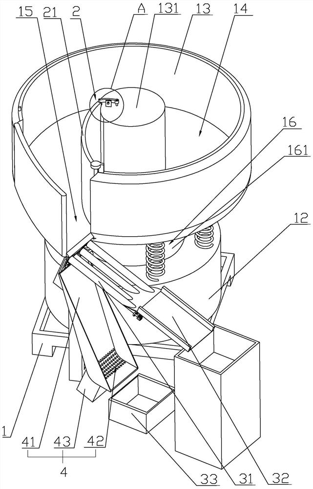
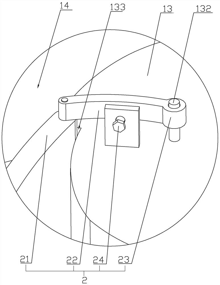
[0048] Embodiment one: refer to figure 1 , is a high-precision oil-impregnated bearing sleeve processing equipment disclosed in the present invention, including a body 1, a vibration seat 12 arranged at the bottom of the body 1, a vibration box 13 arranged at the top of the body 1, and a vibration box 13 arranged between the vibration seat 12 and the vibration box 13. The vibrating mechanism 16 between them and the dispersing mechanism arranged on one side of the vibrating base 12 are used to separate abrasives and workpieces. Vibration box 13 is provided with an annular vibrating cavity 14 for mixing workpieces and abrasives. Vibrating mechanism 16 includes vibrating motor 161 arranged on vibrating base 12. Vibrating motor 161 and vibrating base 12 are fixed by screws. When vibrating motor 161 When starting, the vibrating box 13 is driven to vibrate so that the mixture of the workpiece and abrasive is rotated clockwise or counterclockwise around the vibrating chamber 14 for p...

Embodiment 2

[0061] Embodiment 2: A method for processing a high-precision oil-impregnated bearing sleeve, comprising the following steps:

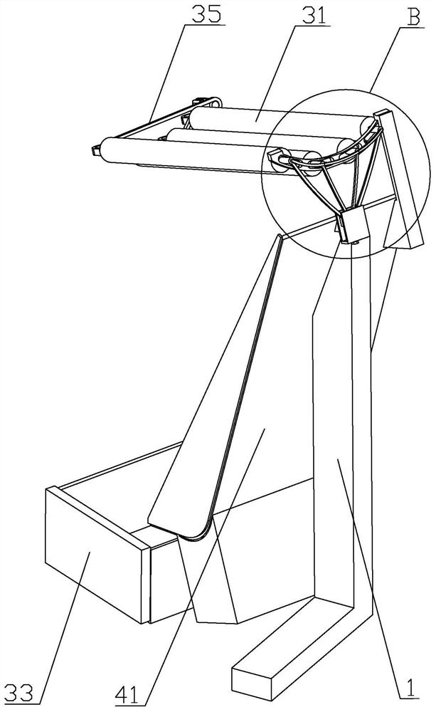
[0062] S100: according to the size of the bearing sleeve, change the clearance of the sieve rod 31 through the slider 34;

[0063] S200: Put the bearing sleeve and the abrasive into the vibration cavity 14 after being mixed, and switch the channel changing plate 21 to a contact position with the outer wall of the vibration cavity 14;

[0064] S300: Turn on the vibration motor 161, and the vibration motor 161 drives the mixture of the workpiece and the abrasive to rotate clockwise or counterclockwise around the ring-shaped vibration chamber 14 and perform vibration polishing, at this time, the bearing sleeve and the abrasive are in an internal circulation state;

[0065] S400: After polishing, turn the channel changing plate 21 to connect with the central column 131, and the mixture of workpiece and abrasive reaches the discharge port 15 along the chan...


PUM


Abstract

The invention relates to a high-precision oil-impregnated bearing sleeve processing equipment and method, and relates to the technical field of powder metallurgy bearing processing, which includes a body, a vibrating seat arranged at the bottom of the body, a vibrating box arranged at the top of the body, a vibrating seat and a vibrating The vibration mechanism between the boxes and the dispersing mechanism for separating abrasives and workpieces on one side of the vibrating seat. There is a ring-shaped vibration cavity for mixing workpieces and abrasives in the vibration box. The vibration mechanism is used to drive vibration. The box vibrates so that the mixture of the workpiece and the abrasive is rotated clockwise or counterclockwise around the vibrating chamber to be transported and polished, and a discharge port is opened on one side of the vibrating box. The invention has the effect of improving discharge efficiency and separation efficiency.

Description

technical field [0001] The invention relates to the technical field of powder metallurgy bearing processing, in particular to a high-precision oil-impregnated bearing sleeve processing equipment and method. Background technique [0002] At present, oil-impregnated bearings, that is, porous bearings, are sintered bodies made of metal powder as the main raw material by powder metallurgy. The porosity of the sintered body is used to impregnate it with a volume fraction of 10% to 40%. Lubricating oil can be used in self-supplied state. With the continuous development of the oil-impregnated bearing industry, more and more industries and enterprises have applied oil-impregnated bearings. [0003] The basic structure of an existing bearing includes four parts, an inner ring, an outer ring, rolling elements (steel balls or rollers) and a cage. The outer ring is also called the bearing sleeve, and its inner wall must roll or slide relative to the rolling elements (steel balls or ro...

Claims


Application Information

Patent Timeline
Patent Type & Authority Patents(China)
IPC IPC(8): B24B31/073B24B31/12B24B31/16
CPCB24B31/073B24B31/12B24B31/16
Inventor 宦有强李峰程建平
Owner 深圳市冠强粉末冶金制品有限公司
Why Eureka
Try Eureka