

An emergency window structure for a high-speed train
A technology for high-speed trains and windows, which is applied in the field of passenger compartment windows, can solve the problems affecting passenger ride comfort and physical and mental health, breakage, damage to railway driving equipment, etc., and achieves the convenience of height adjustment and glass fixing, installation and disassembly. The effect of speed and ensuring the safety of train operation
- Summary
- Abstract
- Description
- Claims
- Application Information
AI Technical Summary
Problems solved by technology
Method used
Image

Examples
Embodiment 1
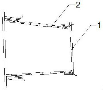
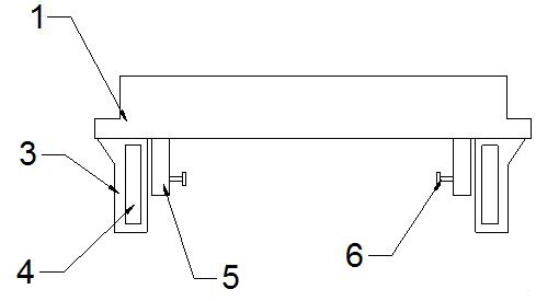
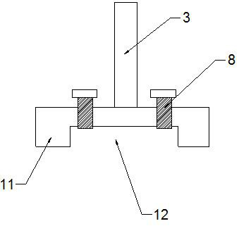
[0042] like Figure 1-4 As shown, an emergency window structure of a high-speed train includes a bracket 1 and an adjustment rod 2. The bracket 1 is provided with two upper and lower sides, and the left and right ends of the two brackets 1 are connected to the adjustment rod 2. The bracket 1 Flanges 11 are symmetrically arranged on both sides along the length direction of one side of the bracket 1, and a groove 12 is formed between the two flanges 11 of the bracket 1. On the bracket 1, between the two flanges 11, on both sides of the mounting plate 3 Two fastening screws 8 are arranged symmetrically. A sleeve 5 and a mounting plate 3 are provided on the side of the bracket 1 away from the flange 11. The side of the sleeve 5 away from the mounting plate 3 is provided with an anti-loosening screw 6. The telescopic rod 23 threaded connection sleeves 5.
[0043] The adjusting rod 2 includes a threaded sleeve 21 and a telescopic rod 23. Both ends of the threaded sleeve 21 are conn...
Embodiment 2
[0046] On the basis of Example 1, combined with Figure 5 , an emergency window structure for a high-speed train, comprising a bracket 1 and an adjustment rod 2, the bracket 1 is provided with two upper and lower sides, the left and right ends of the two brackets 1 are connected to the adjustment rod 2, one of the brackets 1 Flanges 11 are symmetrically arranged on both sides of the side along the length direction, and grooves 12 are formed between the two flanges 11 of the support 1. Two fastening screws 8, the side of the bracket 1 away from the flange 11 is provided with a sleeve 5 and the mounting plate 3, the side of the sleeve 5 away from the mounting plate 3 is provided with an anti-loosening screw 6, and the telescopic rod 23 is threaded Connect sleeve 5.
[0047] The adjusting rod 2 includes a threaded sleeve 21 and a telescopic rod 23. Both ends of the threaded sleeve 21 are connected to the telescopic rod 23 through an adjusting nut 22, and the side of the telescop...
Embodiment 3
[0054] On the basis of Example 2, the external dimensions of the blocking bracket and the adjusting rod are 1962mm×813mm, the total weight of the bracket and the adjusting rod is less than 44kg, the size of the glass is 2008mm×857mm, and the glass structure is: 4mm chemically tempered glass+0.76mmPVB+ 3mm physical tempered glass (outer sheet) + 16mm air layer + 4mm physical tempered glass.
PUM
 Abstract
Description
Claims
Application Information