Hold-down conveying roller and groove roller matched with hold-down conveying roller

A technology of conveying rollers and cooperating rollers, which is applied in the direction of winding strips, thin material handling, transportation and packaging, etc., can solve the problems of inconvenient collection of materials, sagging materials, insufficient tension, etc., and achieves long duration and improved clamping. force, the effect of improving rigidity

Pending Publication Date: 2020-06-19
温州超旺机械有限公司
View PDF0 Cites 0 Cited by
  • Summary
  • Abstract
  • Description
  • Claims
  • Application Information

AI Technical Summary

Problems solved by technology

[0003] In the field of packaging machinery conveying such as woven bags and plastic bags, due to the thinner thickness and high softness of the conveyed materials, during the conveying process, since the conveying components are usually conveyed by two conveying rollers with clearance fit and oppositely arranged, Due to the constraints of the gap, the conveyed material is difficult to be clamped by the two conveying rollers set with the gap, so in actual use, it often occurs that the material between the front and rear conveying positions sags and the tension is insufficient; and On the outlet side of the material, the material is also easy to fit the outer circle of the roller and fall, which is not convenient for further processing in the subsequent process, nor is it convenient for collecting the material

Method used


Image

  • Hold-down conveying roller and groove roller matched with hold-down conveying roller
  • Hold-down conveying roller and groove roller matched with hold-down conveying roller
  • Hold-down conveying roller and groove roller matched with hold-down conveying roller

Examples


Embodiment 1

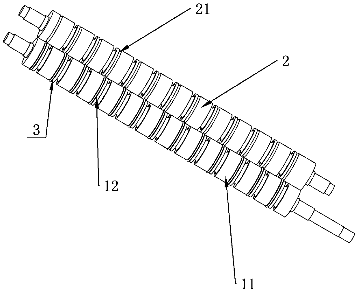
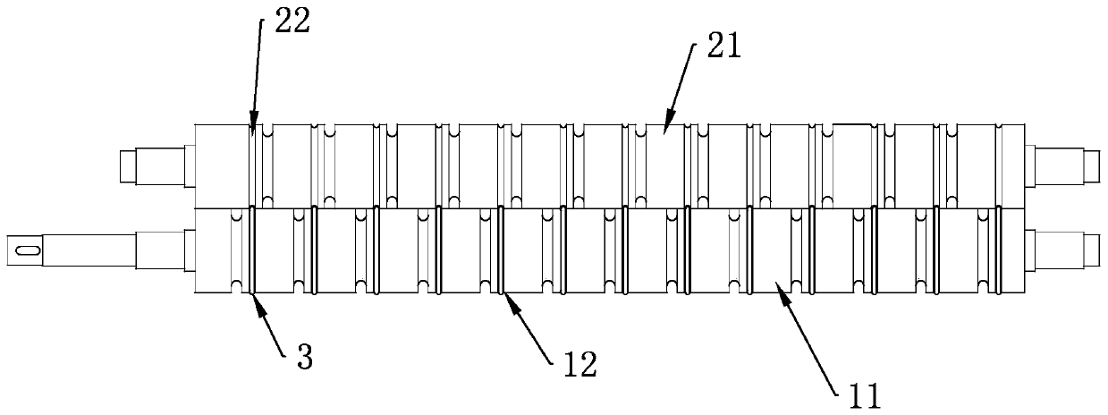
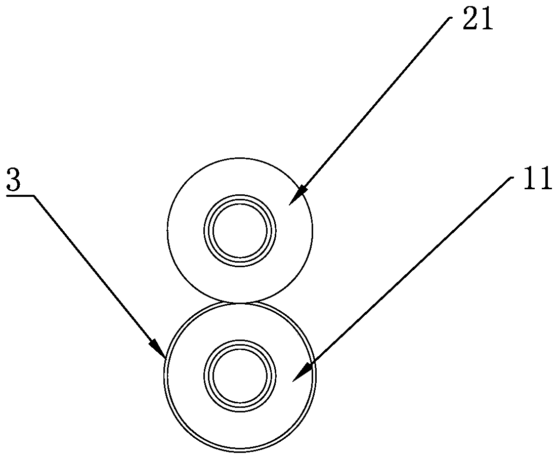
[0057] Embodiment 1 refers to the structure of a pressing conveying roller shown in the accompanying drawings, comprising a columnar roller body 11 and transmission shafts arranged on both end faces of the roller body 11, and the outer surface of the roller body 11 is provided with a plurality of concaves. Groove 12, the groove 12 is an annular groove, which is arranged around the roller body 11 parallel to the radial plane of the roller body 11, and the groove 12 is provided with a spring bar 3 that coincides with the path of the groove 12.

[0058] The spring bars 3 are fixed end to end by welding to prevent the spring bars 3 from coming off during use. It can be seen intuitively from the drawings that the surface of the spring bar 3 protrudes from the surface of the roller body 11. In this embodiment, in order to make the whole stable and balanced, the spring bar 3 preferably adopts equidistant springs with constant diameters. The spring bar 3 can be made of steel alloy or ...

Embodiment 2

[0062] Embodiment 2 The difference between this embodiment and Embodiment 1 is that the ring groove is or is inclined to the radial plane of the roller body 11, that is, in this embodiment, the groove 12 is an inclined groove. Correspondingly, the embodiment The groove 12 in 1 is a straight groove.

Embodiment 3

[0063] Embodiment 3 The difference between this embodiment and the above embodiment is that the groove 12 is a spiral groove, which is the effect of protruding the spring bar 3. The number of spiral grooves is preferably more than two, and the parallel distribution is the first. A staggered distribution can also be used. However, under the staggered distribution, in order to make the roller body 11 rotate and convey the material, it is best to maintain the same force on the material every time it passes. It is necessary to control the number and appropriate spacing of the spiral grooves used in the staggered distribution according to the actual situation.


PUM


Abstract

The invention relates to a hold-down conveying roller and a groove roller matched with the hold-down conveying roller. The hold-down conveying roller comprises a roller body and transmission shafts arranged on the end faces of two ends of the roller body, the roller body is provided with grooves, spring strips matched with the grooves are arranged in the grooves, and the surfaces of the spring strips protrude out of the surface of the roller body. The groove roller comprises a matching roller body and transmission shafts arranged on the end faces of two ends of the matching roller body, the surface of the matching roller body is provided with matching grooves, and the positions of the matching grooves correspond to the positions of the grooves of any hold-down conveying roller described inclaims 1-9. The hold-down conveying roller and the groove roller matched with the hold-down conveying roller can improve the condition of clamping thin and soft materials by two conveying rollers inrelative clearance fit to ensure the tensioned state of the materials during conveying, and the linkage of conveying and subsequent processing stations is better facilitated.

Description

technical field [0001] The invention relates to the technical field of mechanical transmission rollers, in particular to a pressing transmission roller. Background technique [0002] Roller is a cylindrical part, divided into driving and driven rollers, which are widely used in various transmission systems such as rotary screen printing machines, digital printers, mining conveying equipment, papermaking and packaging machinery. Rubber roller is one of them, which is a roller-shaped product made of metal or other materials as the core and covered with rubber through vulcanization. [0003] In the field of packaging machinery conveying such as woven bags and plastic bags, due to the thinner thickness and high softness of the conveyed materials, during the conveying process, since the conveying components are usually conveyed by two conveying rollers with clearance fit and oppositely arranged, Due to the constraints of the gap, it is difficult for the material to be conveyed t...

Claims


Application Information

Patent Timeline
Patent Type & Authority Applications(China)
IPC IPC(8): B65H20/02B65H23/188B65H27/00B65H23/34
CPCB65H20/02B65H23/1888B65H23/34B65H27/00B65H2701/1133B65H2801/81
Inventor 陈其管黄步积
Owner 温州超旺机械有限公司
Why Eureka
Try Eureka