Constant-current source intelligent control cabinet for crude oil electric dehydration
An intelligent control cabinet and electric dehydration technology, applied in the field of control cabinets, can solve the problems of difficulty in adapting to the complex on-site environment of crude oil dehydration production, no intelligent control mode, low device integration, etc., achieving flexible and convenient control modes and improving explosion-proof grades. and safety, and the effect of improving reliability
- Summary
- Abstract
- Description
- Claims
- Application Information
AI Technical Summary
Problems solved by technology
Method used
Image

Examples
Embodiment Construction
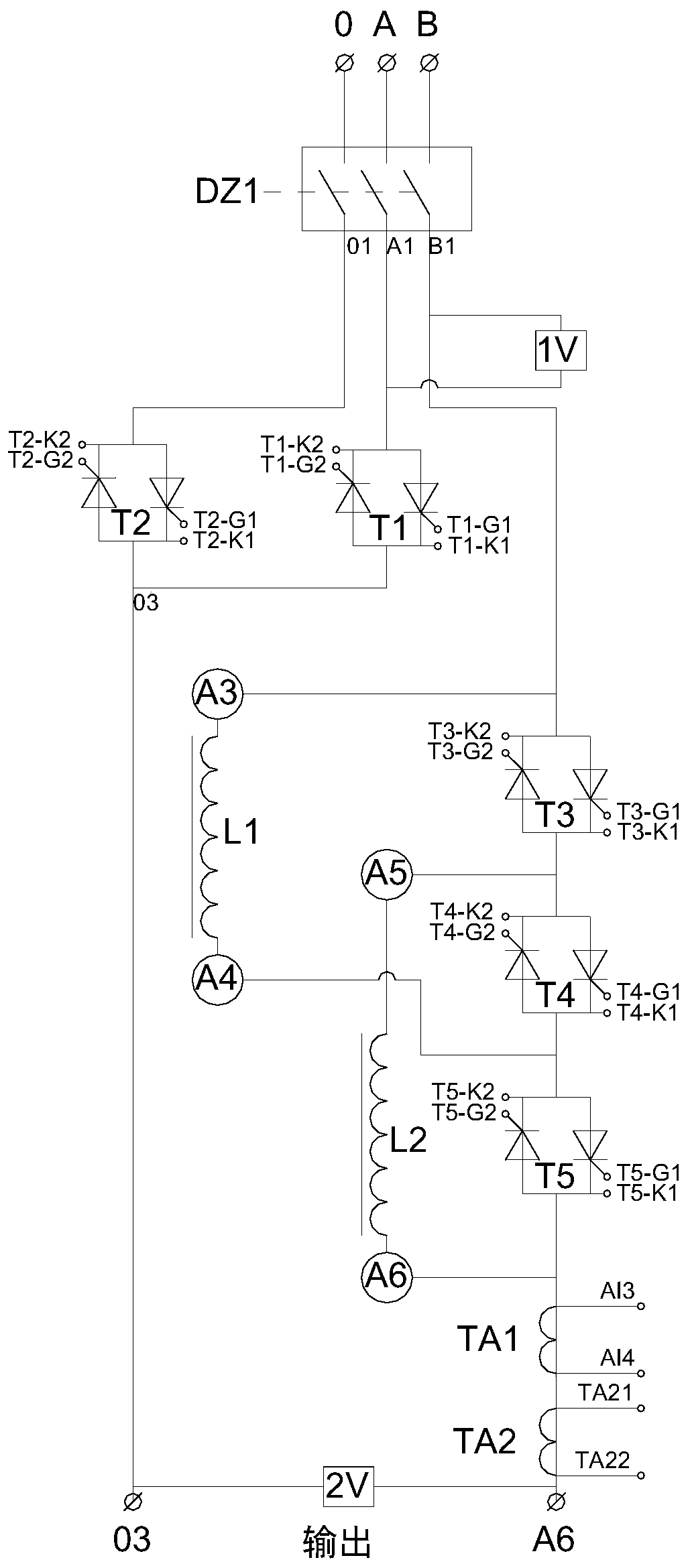
[0017] The specific structure of the intelligent control cabinet of the present invention will be further described in detail below in conjunction with the accompanying drawings.
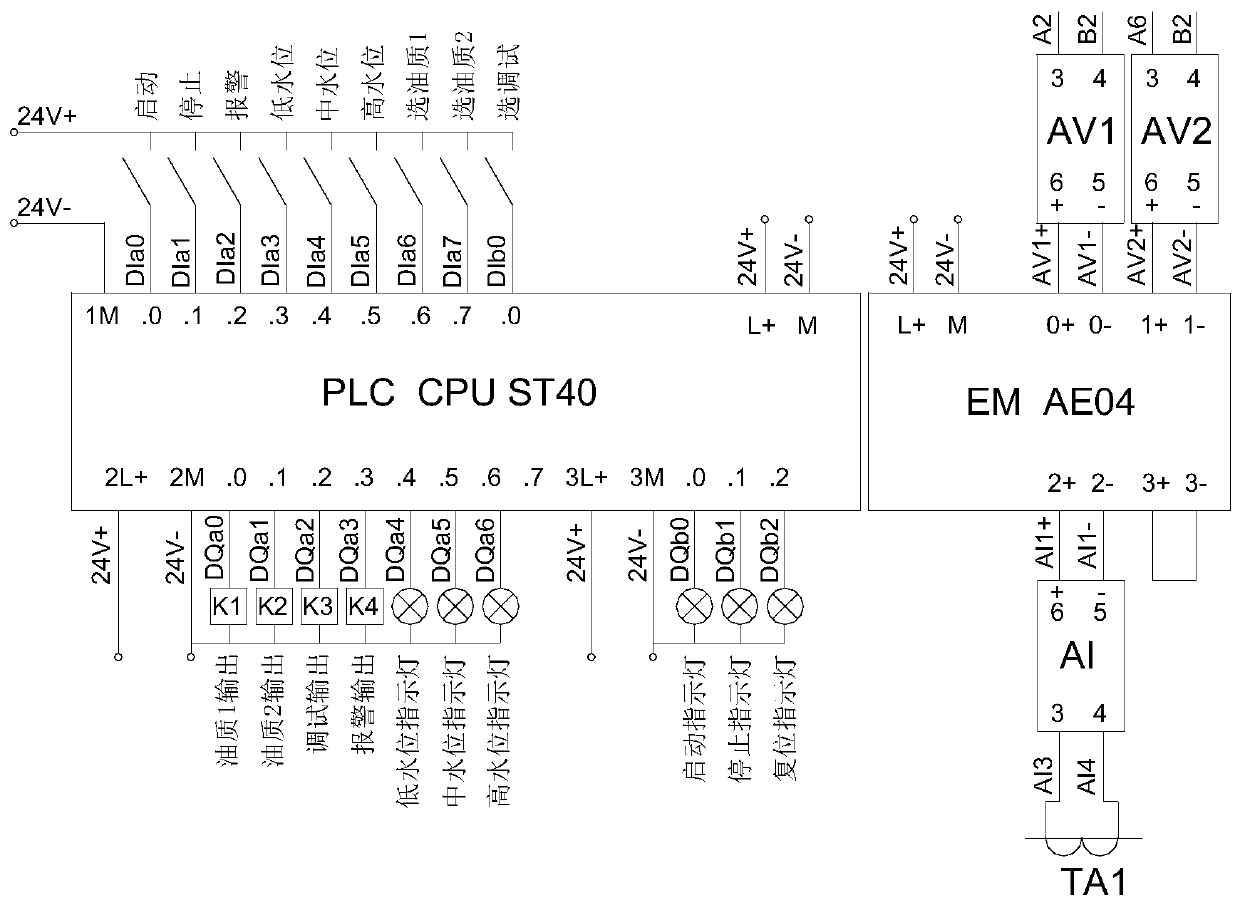
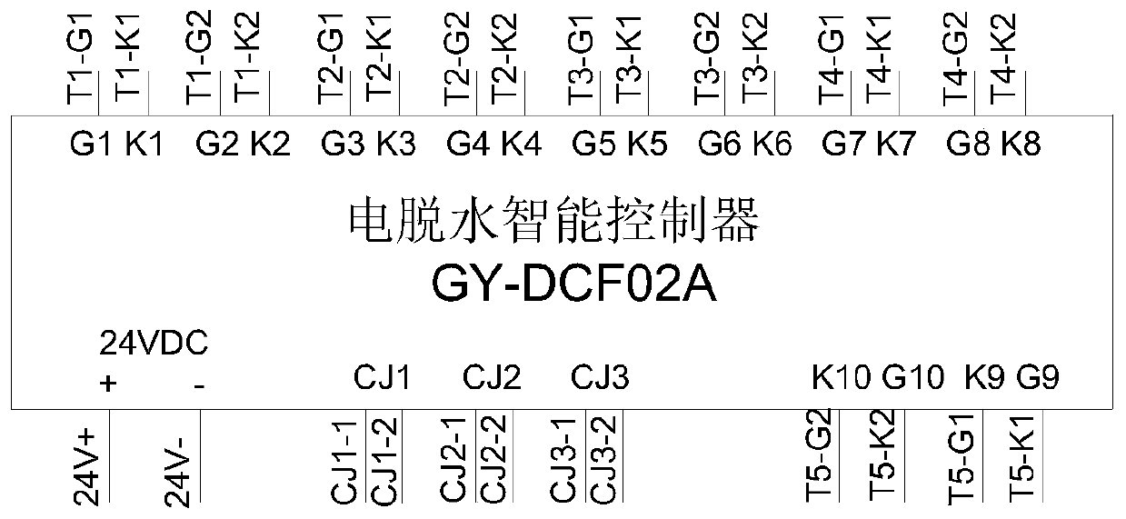
[0018] Such as figure 1 with figure 2 shown. The constant current source intelligent control cabinet for electric dehydration of crude oil of the present invention is composed of a cabinet body, a power supply main circuit and a control circuit installed in the cabinet body. The main circuit of the power supply is connected with a thyristor device as a switch to control the on-off of the main circuit. The selection control of the inductor in the main circuit is also controlled by the thyristor device as a switch. The opening and closing of each thyristor device is controlled by an intelligent dedicated controller. Control, and the detection, display and control devices used for working status are all connected to a PLC controller for control.
[0019] The thyristors are controlled by a dedicated...
PUM
 Abstract
Description
Claims
Application Information
PatSnap Eureka turns technology decisions into work you can execute. Powered by our Innovation Knowledge Graph, it runs expert workflows across engineering, life sciences, materials and intellectual property. Get your review-ready output in minutes.


