
A spud shoe of a jack-up drilling platform

A drilling platform, self-elevating technology, applied to sheet pile walls, buildings, foundation structure engineering, etc., can solve problems affecting the bearing capacity of pile legs, broken flow, platform tilt, etc.

Active Publication Date: 2021-08-20
义乌市铂川建筑工程有限公司
View PDF0 Cites 0 Cited by
  • Summary
  • Abstract
  • Description
  • Claims
  • Application Information

AI Technical Summary

Problems solved by technology

[0003] The existing spud cans need to bear a very large weight, and the structure of the spud cans is relatively simple, so in order to make the spud cans bear a greater platform weight, the size of the spud cans must be increased. Once the size is increased , the overall weight of the spud boots will increase, so the depth of the spud boots into the mud will also increase, and the increase in the depth of the piles into the mud will make it more difficult to pull out the piles in the later stage, and because the pile legs will be impacted by ocean currents on the seabed , which will drive the spud cans to slide laterally on the seabed. Due to the simple structure of the existing spud cans, the stability of the spud cans can only be increased by increasing the size of the spud cans. Once one of the spud cans slides, due to the existing Some spud boots are too large, the inertia will be greater when moving, and the driving force will be greater, which will cause other spud boots to slide together, resulting in a horizontal force on the spud legs, which is serious It affects the bearing capacity of the pile legs, and once the horizontal force on the pile legs exceeds the critical value, the pile legs will be bent or even cut off in a short period of time, causing the entire platform to tilt, which poses a huge safety hazard

Method used


Image

  • A spud shoe of a jack-up drilling platform
  • A spud shoe of a jack-up drilling platform
  • A spud shoe of a jack-up drilling platform

Examples


Embodiment Construction

[0021] The following will clearly and completely describe the technical solutions in the embodiments of the present invention with reference to the accompanying drawings in the embodiments of the present invention. Obviously, the described embodiments are only some, not all, embodiments of the present invention. Based on the embodiments of the present invention, all other embodiments obtained by persons of ordinary skill in the art without making creative efforts belong to the protection scope of the present invention.

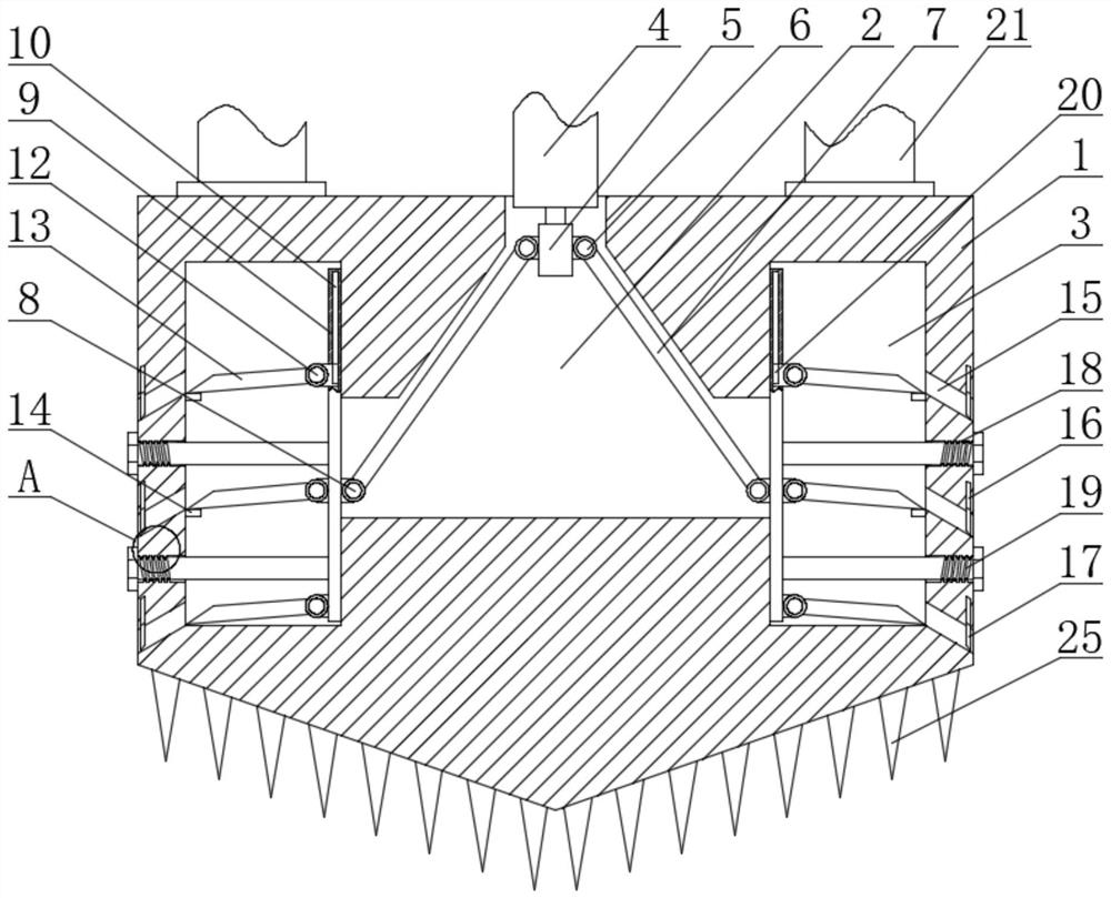
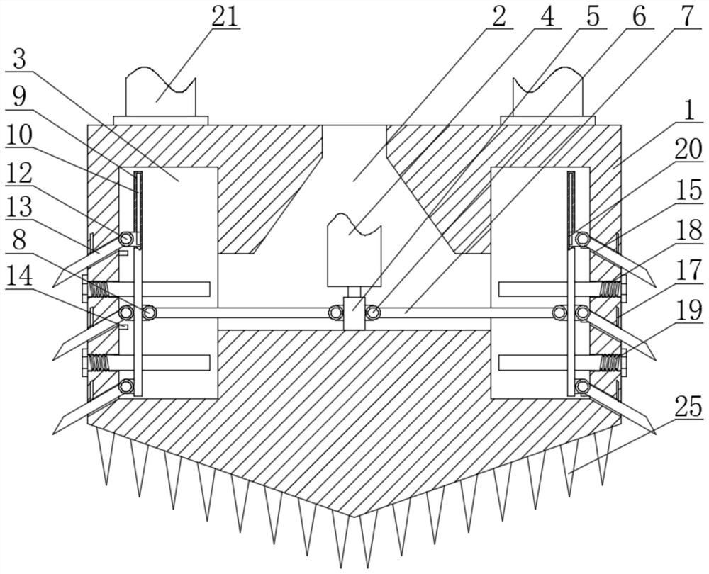
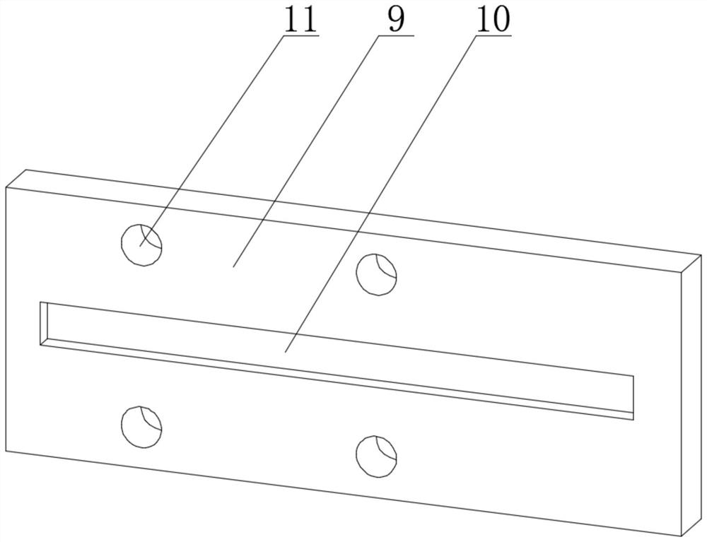
[0022] see Figure 1-7 , a spud shoe for a jack-up drilling platform, comprising a spud shoe 1, a central cavity 2 is provided in the middle of the spud shoe 1, and side cavities 3 are respectively provided inside the spud shoe 1 on both sides of the central cavity 2, The central cavity 2 communicates with the side cavity 3, and the top of the central cavity 2 is provided with a cylindrical opening that matches the shape of the transmission long rod 4. The tra...


PUM


Abstract

The invention relates to the technical field of offshore drilling platforms, and discloses a spud can of a self-elevating drilling platform, comprising a spud can, and a central cavity is opened in the middle of the interior of the spud can. The spud can of the jack-up drilling platform has a central cavity and side cavities respectively in the center of the spud can and on both sides, so that the overall weight of the spud can is lighter, which reduces the difficulty of the spud can when pulling out piles , by setting a linkage mechanism inside the central cavity and the side cavity, by stretching or pressing down the transmission long rod connected to the platform, the side rods on both sides inside the spud can be contracted or stretched out. , can reduce the resistance of the spud boot during pile extraction, and further reduce the difficulty of pile extraction. When extended, a lateral gripping structure can be formed on both sides of the spud boot, combined with the gripping thorns at the bottom, so that the spud boot as a whole can not only Grasping the bottom of the sea stably also improves the overall ability of the spud can to cope with the force in the horizontal direction.

Description

technical field [0001] The invention relates to the technical field of offshore drilling platforms, in particular to a spud can of a jack-up drilling platform. Background technique [0002] The jack-up drilling device is mainly composed of the main hull of the platform, pile legs and pile foundations. The device of the main hull of the platform will bear all the weight of the two and the weight of the mining equipment on the platform, and the spud boots need to be inserted into the seabed soil to fix the upper platform, so whether the spud boots can play their role normally will depend on It directly affects the normal work of the drilling platform, so the spud shoe is an important structure related to the safety of the platform, but the existing spud shoe always has the following problems during use: [0003] The existing spud cans need to bear a very large weight, and the structure of the spud can is relatively simple, so in order to make the spud can bear a greater platf...

Claims


Application Information

Patent Timeline
IPC IPC(8): E02D5/72
CPCE02D5/72
Inventor 古香义
Owner 义乌市铂川建筑工程有限公司
Learn More