
Sound insulation device

A technology of sound insulation device and sound insulation felt, which is applied in the directions of sound insulation, insulation layer, building components, etc., can solve the problems of inability to limit sound transmission in all directions, poor sound insulation effect, etc., and achieve the effect of reducing vibration and weakening strength.

Inactive Publication Date: 2020-06-19
广州绘声建筑材料有限公司
View PDF8 Cites 3 Cited by
  • Summary
  • Abstract
  • Description
  • Claims
  • Application Information

AI Technical Summary

Problems solved by technology

Therefore, it is often necessary to set up a soundproof room in places with quiet requirements. The traditional soundproof room can only install or spray sound-absorbing materials on the walls, which cannot limit the sound transmission in all directions, and the sound insulation effect is poor.

Method used


Image

  • Sound insulation device
  • Sound insulation device
  • Sound insulation device

Examples


Embodiment 1

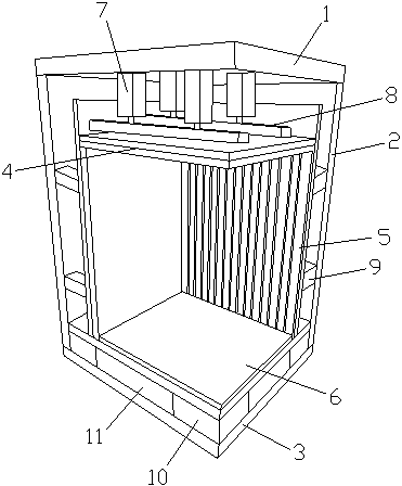
[0037] Such as figure 1 As shown, the present invention provides a sound insulation device, comprising an upper base plate 1, a side base plate 2 and a lower base plate 3, a first upper sound insulation felt 12 is installed on the inner side of the upper base plate 1, and a sound insulation top plate 4 is provided on the inner side of the upper base plate 1, The inner surface of the side base plate 2 is provided with a first side sound-insulating felt 13, the inner side of the side base plate 2 is provided with a sound-insulating side plate 5, the inner side of the lower base plate 3 is provided with a sound-insulating bottom plate 6, a sound-insulating top plate 4, a sound-insulating side plate 5 and a sound-insulating bottom plate 6 A sealed space is formed, a first keel 8 is installed on the outer surface of the sound-insulating top plate 4, a first damping device 7 is installed between the first keel 8 and the upper base plate 1, and a second keel 14 is installed on the out...

Embodiment 2

[0039] Present embodiment 2 adopts following preferred scheme on the basis of embodiment 1:

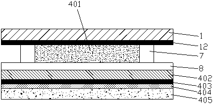
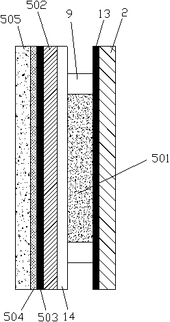
[0040] Such as figure 2As shown, specifically, the sound insulation roof 4 includes a first sound insulation board 402 and a first sound absorption board 405, the first sound insulation board 402 is connected to the first keel 8, and the lower end of the first sound insulation board 402 is provided with a second upper sound insulation felt 403, The second upper sound insulation felt 403 is installed and connected with the bottom surface of the first sound insulation material 401, and the first woodworking board 404 is arranged between the second upper sound insulation felt 403 and the first sound absorbing board 405, and the first wood working board 404 and the first sound absorbing board 405 Adhesive connection, the first sound insulation material 401 is filled between the first keel 8 and the first upper sound insulation felt 12, the first sound insulation material 401 is sound ins...


PUM


Abstract

The invention particularly discloses a sound insulation device. The sound insulation device comprises an upper base plate, a side base plate and a lower base plate. A sound insulation top plate is arranged on the inner side of the upper base plate, and a sound insulation side plate is arranged on the inner side of the side base plate. A sound insulation bottom plate is arranged on the inner side of the lower base plate. A sealed space is formed by the sound insulation top plate, the sound insulation side plate and the sound insulation bottom plate. A first keel is mounted on the outer side face of the sound insulation top plate. A first damping device is arranged between the first keel and the upper base plate. A second keel is mounted on the outer side face of the sound insulation side plate. A second damping device is arranged between the second keel and the side base plate. Damping bricks are arranged between the lower base plate and the sound insulation bottom plate. The sound insulation device is reasonable in design, good in sound insulation effect and capable of weakening the intensity of sound spreading along different media and different directions in an all-dimensional manner.

Description

technical field [0001] The invention relates to the technical field of building materials, in particular to a sound insulation device. Background technique [0002] Most of the residents in the city now live in high-rise buildings, which are very concentrated. In addition, in order to reduce the load-bearing of the buildings, the sound insulation components of the current high-rise buildings are made of various lightweight materials, and the sound insulation performance is poor. If a resident plays a musical instrument in the house, the sound from the musical instrument will often affect the rest of the surrounding neighbors. Therefore, it is often necessary to set up a soundproof room in places where there is a need for quietness. The traditional soundproof room can only install or spray sound-absorbing materials on the walls, which cannot limit the sound transmission in all directions, and the soundproof effect is poor. [0003] For this reason, we propose a kind of sound...

Claims


Application Information

Patent Timeline
IPC IPC(8): E04H1/12E04B1/82E04B1/86E04B1/98E04B1/66
CPCE04B1/66E04B1/82E04B1/86E04B1/98E04H1/125
Inventor 黄兴健谢乃东
Owner 广州绘声建筑材料有限公司
Learn More