Cooling water pump for automobile engine

A technology of automobile engine and cooling water pump, which is applied in the direction of engine cooling, engine components, machines/engines, etc. It can solve the problems affecting the normal circulation of coolant and the normal operation of the pump body, so as to improve the heat dissipation and cooling effect and the service life Long, smooth circulation effect

Pending Publication Date: 2020-06-19
DAFENG HAINA MACHINERY
View PDF0 Cites 0 Cited by
  • Summary
  • Abstract
  • Description
  • Claims
  • Application Information

AI Technical Summary

Problems solved by technology

[0005] The technical problem to be solved by the present invention is that when the engine operates under high temperature conditions, there are often tiny agglomerated substances in the coolant, which are sucked into the pump body, which is not conducive to the normal operation of the pump body, and for a long time, such impurities will adhere to the On the inner wall of the pump body, thus affecting the normal circulation of the coolant

Method used


Image

  • Cooling water pump for automobile engine
  • Cooling water pump for automobile engine
  • Cooling water pump for automobile engine

Examples


Embodiment Construction

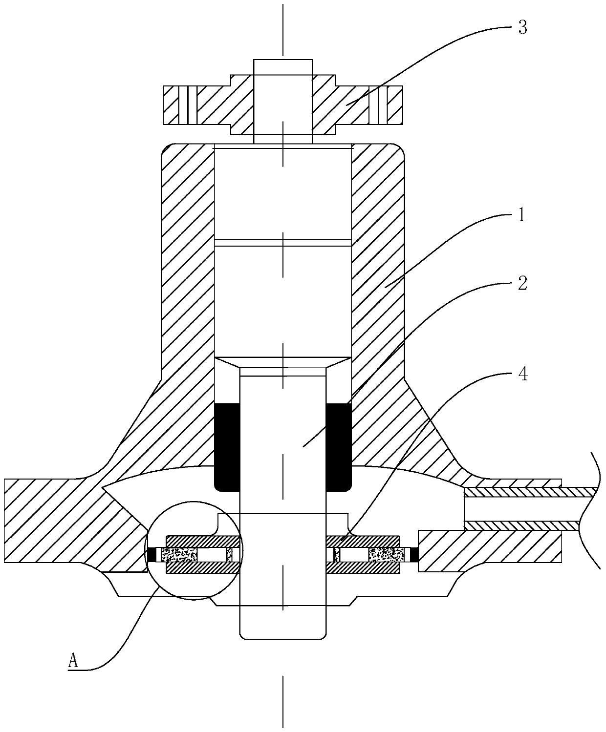
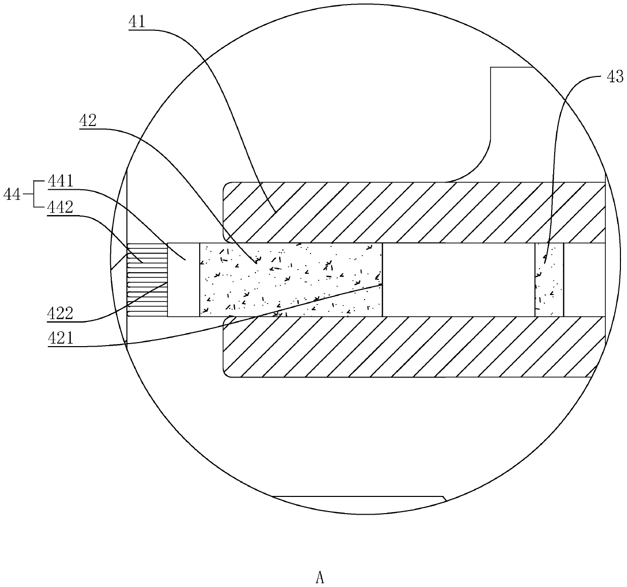
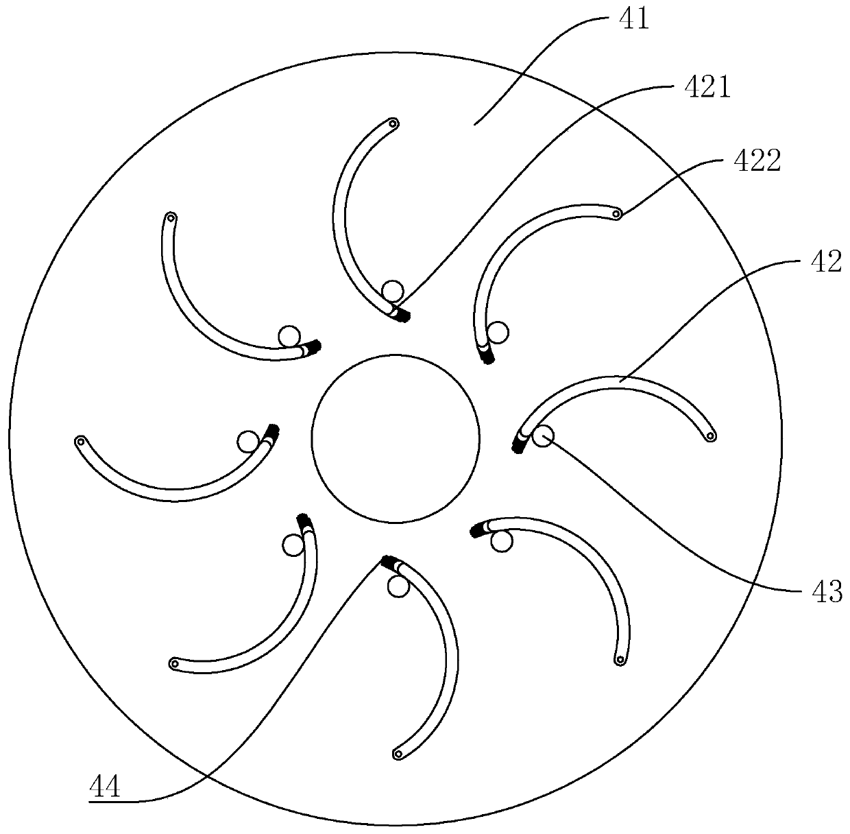
[0023] The cooling water pump for an automobile engine provided in this embodiment has a structure such as Figure 1 to Figure 4 As shown, the pump body 1 is included. The inner interference fit of the pump body 1 is provided with a shaft-connected bearing 2 and the upper and lower ends of the shaft-connected bearing 2 are respectively connected with a flange 3 and an impeller device 4. The impeller device 4 includes two circular clamping plates 41 parallel to each other. The two circular clamping plates 41 are arranged at intervals in the vertical direction. A number of blades 42 are rotatably connected between the two circular clamping plates 41. The rotation of the blades 42 The shaft is arranged in the vertical direction and is arranged at the end of the blade 42 itself close to the outer side of the impeller. A number of limit posts 43 are connected between the two circular clamping plates 41. The limit posts 43 are used to conflict with the corresponding blade 42. A clean...


PUM


Abstract

The invention discloses a cooling water pump for an automobile engine, and relates to the technical field of water pumps. When the cooling water pump is normally used, an impeller rotates in the normal direction, due to the fact that blades are rotationally connected to a circular clamping plate and under the inertia effect, the blades and the circular clamping plate move relatively, and the blades tend to move towards the side deviating from the rotating direction of the impeller; due to the arrangement of the limiting columns, the blades abut against the limiting columns, so that the bladesdo not move and normally play a role in circulating cooling water; after the cooling water pump is used for a long time, due to the fact that impurities in cooling water adhere to the inner wall of the pump body, the impeller is reversely driven at the moment, under the action of inertia and centrifugal force, the inner ends of the blades rotate out of the impeller, namely the cleaning brushes rotate out of the impeller and abut against the inner wall of the pump body, and therefore the inner wall of the pump body is conveniently wiped; therefore, the cleaning effect is achieved, the pump bodycan work normally after being used for a long time, and circulation of cooling liquid is smoother.

Description

Technical field [0001] The invention relates to the technical field of water pumps, in particular to a cooling water pump for automobile engines. Background technique [0002] In the cylinder block of a car engine, there are multiple water channels for the circulation of cooling water, which are connected with the water tank placed in the front of the car through water pipes to form a large water circulation system. The cooling water pump is located at the upper water outlet of the engine, and the engine passes through the pulley. Drive, pump out the hot water in the engine block water channel, and pump in the cold water. There is a thermostat next to the water pump. When the car is just started (that is, the car is cold), it is not turned on, so that the cooling water does not pass through the water tank, but only circulates in the engine. When the temperature of the engine reaches 95 degrees or more, it will turn on. The hot water inside is pumped into the water tank, and the ...

Claims


Application Information

Patent Timeline
Patent Type & Authority Applications(China)
IPC IPC(8): F04D29/22F04D29/24F04D29/70F01P5/10
CPCF01P5/10F04D29/2261F04D29/2283F04D29/242F04D29/247F04D29/708
Inventor 王华生
Owner DAFENG HAINA MACHINERY
Why Eureka
Try Eureka