Novel continuous melting material melting equipment

A melting and new type of technology, applied in the direction of feeding device, chemical industry, climate sustainability, etc., can solve the problems of wasting steam, dirty discharge and reducing the service life of equipment, etc.

Pending Publication Date: 2022-05-17
沙县森明工贸有限公司
View PDF0 Cites 0 Cited by
  • Summary
  • Abstract
  • Description
  • Claims
  • Application Information

AI Technical Summary

Problems solved by technology

[0007] During the use of low-hour static autoclaves, a certain thickness of melt will be produced on the top of the grid plate. These solids are easy to block the grid plate, so that the melted liquid water glass cannot enter the bottom through the grid plate and discharge from the discharge pipe. Only after the pressure is released through the vent pipe, the melt on the grid plate can be cleaned up again, which not only causes waste of steam but also affects the production capacity of the equipment
Although the drum is designed without a grid plate, there are turning plates distributed inside the drum. Using the rotation of the drum itself can turn up the material, allowing the material to be fully and evenly heated and melted, avoiding the defects of the static autoclave. After feeding, some materials are deposited in the tank, and the subsequent cleaning will also cause steam waste and affect a small part of the equipment's production capacity.
[0008] These two types of equipment have a common problem: before each loading, the pressure and temperature in the equipment must be lowered to an operable state to load the material, and then repeat the previous steps after loading the material: add steam, heat up, and repeat. , wasting a lot of steam
At the same time, due to the unclean cooling and discharge, some bottom materials are deposited at the bottom of the equipment. When the equipment drops to normal temperature, the accumulated liquid will cause agglomeration due to the lower temperature and the delay in subsequent feeding and liquid heating. Resulting in a decrease in the production capacity of a single device
When the scale is hit by an external force of the air hammer, it cannot be completely cleaned, which will cause great damage to the material of the equipment body and reduce the service life of the equipment.

Method used


Image

  • Novel continuous melting material melting equipment
  • Novel continuous melting material melting equipment
  • Novel continuous melting material melting equipment

Examples


Embodiment 1

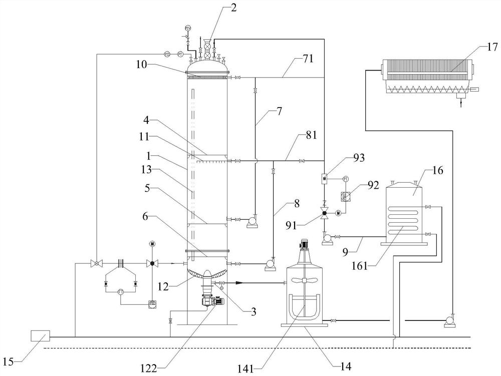
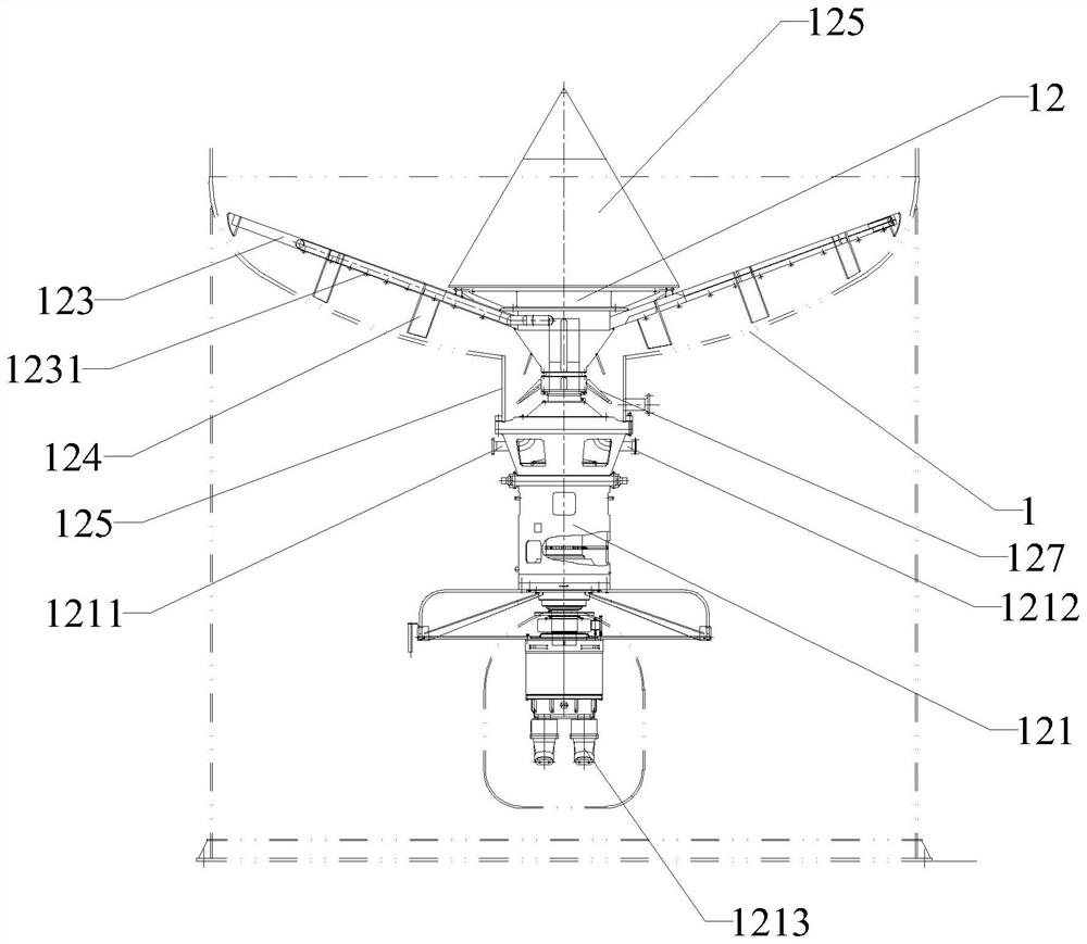
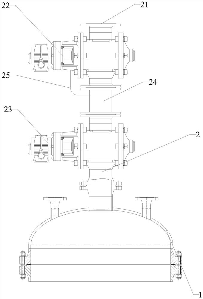
[0052] Please refer to Figure 1 to Figure 3 , a new type of continuous melting material equipment, including:

[0053] Chemical material tank body 1, the chemical material tank body 1 is cylindrical with the axial direction being vertical;

[0054] Feeding device 2, the feeding device 2 is connected to the top of the chemical tank body 1;

[0055] A discharge port 3, the discharge port 3 is arranged at the bottom of the chemical tank body 1;

[0056] The first sieve plate 4, the first sieve plate 4 is arranged inside the chemical tank body 1;

[0057] The second sieve plate 5, the second sieve plate 5 is arranged inside the chemical material kettle body 1, the second sieve plate 5 is located below the first sieve plate 4, and the sieve hole of the second sieve plate 5 is smaller than the first sieve plate 5 A sieve hole of the sieve plate 4;

[0058] The third sieve plate 6, the third sieve plate 6 is arranged inside the chemical material kettle body 1, the third sieve pl...

Embodiment 2

[0082] The novel continuous melting material equipment described in embodiment 1, wherein, also includes:

[0083] A slurry buffer tank 14 , the liquid inlet end of the slurry buffer tank 14 communicates with the discharge port 3 of the chemical tank body 1 ;

Embodiment 3

[0085] In the novel continuous melting material equipment described in Example 1, the discharge port 3 is provided with an electric control valve.


PUM


Abstract

The invention relates to the technical field of chemical equipment, in particular to novel continuous material melting equipment, an inner cavity of a reaction kettle body is divided into multiple layers of spaces by a first sieve plate, a second sieve plate and a third sieve plate, the aperture of each layer of sieve plate is gradually reduced from top to bottom, and when materials enter the reaction kettle body, the materials fall on the first sieve plate in the kettle. Under the action of high temperature and high pressure, solid water glass is dissolved into liquid water glass, the volume of the solid water glass is gradually reduced, and when the volume is smaller than the aperture of the first sieve plate, the solid water glass falls into the next layer and continues to react with liquid in the kettle. The materials fall to the next layer from the second sieve plate and fall to the lower layer from the third sieve plate in a similar way until the materials are completely dissolved into liquid water glass and then sink to the kettle bottom, and a stirring rod of a scraping device at the kettle bottom always keeps rotating, so that the materials at the bottom can be kept in a flowing state, and meanwhile, an upward flowing direction is generated. Through the improvement of the melting machine equipment, steam can be saved, material blockage can be avoided, and the service life of the equipment is prolonged.

Description

technical field [0001] The invention relates to the technical field of chemical equipment, in particular to a novel continuous melting material equipment. Background technique [0002] Silicon exists mainly in the state of silicon dioxide and silicate in nature. All plants contain a small amount of silicon dioxide, and the connective tissue in animals also contains silicon dioxide. The content of silicon in the earth's crust is absolutely abundant, and the weight percentage of silicon in the earth's crust is 27.6%, second only to oxygen (47.2%). Inorganic silicon compounds were a fast-growing series of inorganic chemicals in the 1980s, especially in recent years. Among the inorganic chemicals in the Derwent Center Patent Index, the number of patent abstracts of silicon compounds occupies an absolute advantage. It can be seen from this that inorganic silicon compounds are obviously competitive among numerous inorganic chemicals. [0003] Looking at the world situation, the...

Claims


Application Information

Patent Timeline
IPC IPC(8): B01J19/00B01J19/18B01D36/00B01J3/02B01J3/04B01J4/00
CPCB01J19/0006B01J3/04B01J3/02B01J4/001B01J4/008B01J4/005B01J19/0013B01J19/002B01J19/0053B01J19/1862B01D36/00B01J2204/002B01J2204/005B01J2219/00006B01J2219/0004B01J2219/00123Y02P20/10
Inventor 何大江
Owner 沙县森明工贸有限公司
Why Eureka
Try Eureka