
Radio astronomical receiver and signal flatness compensation method thereof

A technology for radio astronomy and receiving signals, applied in the fields of electromagnetic field characteristics, measuring electrical variables, instruments, etc., can solve the problem that the flatness compensation method cannot meet the high requirements of real-time observation and processing, and reduce the influence of random unevenness, simple technology and low cost low effect

Active Publication Date: 2020-06-19
SHANDONG UNIV
View PDF7 Cites 2 Cited by
  • Summary
  • Abstract
  • Description
  • Claims
  • Application Information

AI Technical Summary

Problems solved by technology

In addition, according to the special application background of radio astronomy, the current flatness compensation method cannot meet the high requirements of real-time observation processing

Method used


Image

  • Radio astronomical receiver and signal flatness compensation method thereof
  • Radio astronomical receiver and signal flatness compensation method thereof
  • Radio astronomical receiver and signal flatness compensation method thereof

Examples


Embodiment 1

[0030] Embodiment 1. This embodiment provides a signal flatness compensation method for a radio astronomy receiver;

[0031] The signal flatness compensation method of radio astronomy receiver includes:

[0032] S1: The radio astronomy receiver receives the radio frequency signal generated by the signal source;

[0033] S2: Amplify, filter, and digitize the radio frequency signal in sequence to obtain a processed signal;

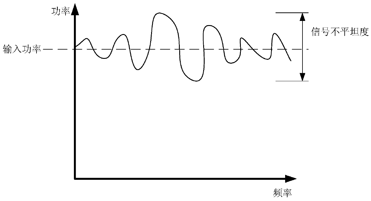
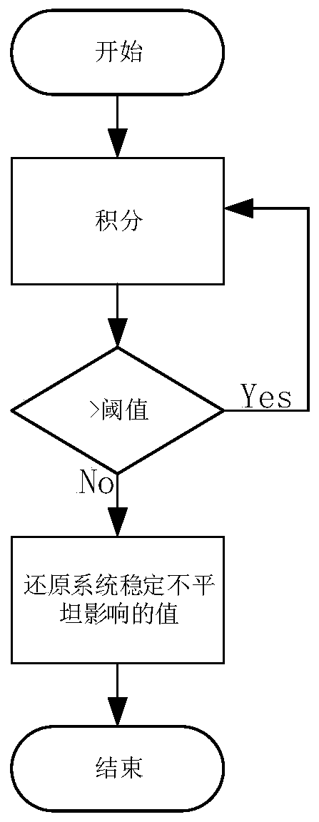
[0034] S3: Eliminate the influence of stable unevenness on the digitally processed signal, reduce the influence of random unevenness, and realize the compensation of signal flatness by the radio astronomy receiver.

[0035] As one or more embodiments, in the S1, the radio astronomy receiver receiving the radio frequency signal generated by the signal source refers to:

[0036] The radio astronomy receiver receives the RF signal with the same amplitude and the frequency change generated by the signal source; suppose the RF power of the RF signal is P in , The frequency...

Embodiment 2

[0070] In the second embodiment, this embodiment also provides a radio astronomy receiver;

[0071] Radio astronomy receivers, including:

[0072] The analog front end receives the radio frequency signal generated by the signal source; the radio frequency signal is sequentially amplified and filtered;

[0073] Analog-to-digital converter ADC, digital processing the signal after amplification and filtering;

[0074] The digital signal processing module is configured to eliminate the influence of stable unevenness on the digitally processed signal, reduce the influence of random unevenness, and realize the compensation of the signal flatness of the radio astronomy receiver.

[0075] As one or more embodiments, the digital signal processing module includes:

[0076] The integration unit is configured to: integrate any frequency point n times; obtain:

[0077] nP in =nP out +nS+(Δ1(t)+Δ2(t)+......+Δn(t)); (1)

[0078] Among them, n represents the number of integrations, and n is a positive ...


PUM


Abstract

The invention discloses a radio astronomical receiver and a signal flatness compensation method thereof. The method comprises the steps that the radio astronomical receiver receives a radio frequencysignal generated by a signal source; amplification filtering processing and digital processing are sequentially carried out on the radio frequency signal to obtain a processed signal; and influence ofstability unevenness on the digitalized signal is eliminated, influence of random unevenness is reduced, and further the radio astronomical receiver compensates the signal flatness. The signal flatness compensation method based on rear-end software real-time compensation is provided for solving the problem that a solar radio observation system has large difference in response to signals with thesame power and different frequencies, and the problem that signals of the solar radio observation system are uneven is specially solved.

Description

Technical field [0001] The present disclosure relates to the technical field of signal flatness compensation, in particular to a signal flatness compensation method of a radio astronomy receiver and a radio astronomy receiver. Background technique [0002] The statements in this section merely mention background technologies related to the present disclosure, and do not necessarily constitute prior art. [0003] The solar radio observation system is an indispensable instrument and equipment for the study of solar radio. The broadband solar radio observation system is an important part of the solar radio observation system. With the advancement of science and technology, the bandwidth of the broadband solar radio observation system is already available Up to a few GHz, the wide-bandwidth solar radio observation system can observe the changes of radio phenomena in different frequencies. However, it is inevitable that the analog front-end responds to the received signal inconsistently...

Claims


Application Information

Patent Timeline
Patent Type & Authority Applications(China)
IPC IPC(8): G01R29/08
CPCG01R29/0814G01R29/0892
Inventor 严发宝徐珂陈耀武昭苏艳蕊尚自乾杨文超
Owner SHANDONG UNIV
Learn More