Radio network controller

a radio network controller and controller technology, applied in the field of radio network controllers, can solve problems such as difficult prediction increase in transmission delay,

Inactive Publication Date: 2005-05-19
FUJITSU LTD
View PDF72 Cites 55 Cited by
  • Summary
  • Abstract
  • Description
  • Claims
  • Application Information

AI Technical Summary

Benefits of technology

[0015] Accordingly, it is a general object of the present invention to provide ...

Problems solved by technology

Further, these are difficult to predict.
However, an increase in the number of nodes to go through causes an increase in transmission delay.
This conversion may cause an increase in transmission delay.
These transmission delays due to IP transmission lines are not constant, and may vary constantly depending on the communications environment.
The retransmission of the normally received signal is an unnecessary retransmission of a signal, so that there is a risk of degradation of transmission efficiency.
This results in a long period of data transmission although high-speed communications with...

Method used


Image

  • Radio network controller
  • Radio network controller
  • Radio network controller

Examples


Embodiment Construction

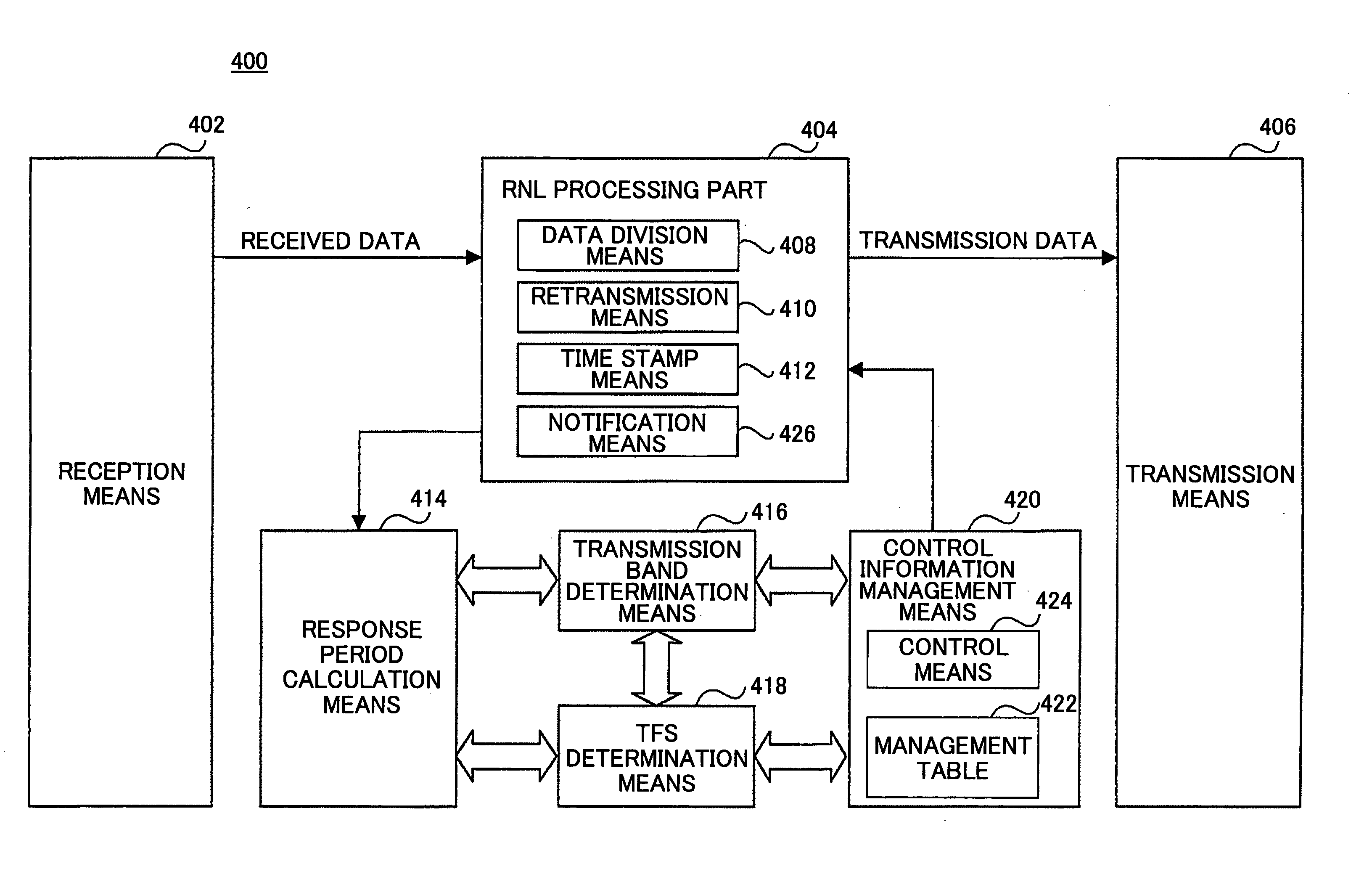
[0030]FIG. 4 is a functional block diagram of a radio network controller 400 employed in a communications system according to an embodiment of the present invention. The radio network controller 400 is commonly used mainly for the radio network controllers 206 and 208 shown in FIG. 3.

[0031] The radio network controller 400 includes reception means 402 for receiving a signal from the switch 204 (FIG. 3) or a subordinate base station, an RNL processing part 404 converting the data received from the switch 204 into transmission data to be transmitted to the subordinate base station, and transmission means 406 for transmitting the transmission data to the base station. The data received from the reception means 402 is divided into signals of a predetermined data size such as 40 octets by data division means 408 of the RNL processing part 404, and the transmission data is formed by the divided signals. Further, the RNL processing part 404 includes retransmission means 410 for retransmit...


PUM


Abstract

A communications system having an ATM transmission line and an IP transmission line is disclosed that includes a base station capable of communicating with a mobile terminal through a radio link; and a radio network controller capable of communicating with the base station through the ATM or IP transmission line. The radio network controller includes a division part dividing transmission data into signals of a predetermined data size; a transmission part transmitting the divided signals to the base station at predetermined time intervals; a retransmission part retransmitting the signals transmitted to the base station when a response signal from the mobile terminal is not received within a predetermined period; a measuring part measuring a signal response period in a communications channel between the radio network controller and the mobile terminal through the base station; and a determination part determining the predetermined data size based on the measured response period.

Description

CROSS REFERENCE TO RELATED APPLICATION [0001] This application is a U.S. continuation application filed under 35 U.S.C. 111(a) claiming benefit under 35 U.S.C. 120 and 365(c) of PCT International Application No. PCT / JP02 / 09127, filed Sep. 6, 2002, the contents of which are hereby incorporated by reference.BACKGROUND OF THE INVENTION [0002] 1. Field of the Invention [0003] The present invention relates to a radio network controller. [0004] 2. Description of the Related Art [0005] In recent years, rapid progress has been made in the research and development of CDMA (Code Division Multiple Access) communications systems, so that not only audio and still images but also a broadband CDMA system (W-CDMA: Wideband CDMA) has emerged. 3GPP (3rd Generation Partnership Project [http: / / www.3gpp.org / ]), which is a standardization group for a 3rd Generation Mobile System, aims to realize a system that can provide high-quality services, developing various W-CDMA communications system standards. [0...

Claims


Application Information

Patent Timeline
IPC IPC(8): H04L1/00H04L1/16H04L1/18H04L47/43H04W28/00H04W28/04H04W28/06H04W28/10H04W88/14H04W92/00
CPCH04L1/0002H04L1/0006H04L1/16H04L1/188H04L12/56H04L69/168H04W28/06H04W80/04H04W88/12H04L69/16H04L69/14H04W28/04
Inventor KOBAYASHI, KAZUNARIKUMAGAI, TOMONORITOMITA, TETSUOIKEDA, EIJI
Owner FUJITSU LTD
Why Eureka
Try Eureka