LED backlight device and display equipment

A backlight device and LED light source technology, applied in optics, nonlinear optics, instruments, etc., can solve problems such as difficulties in the implementation of flexible Mini-LED backlight technology, loss of light return efficiency, low light output efficiency, etc., to improve light uniformity and light output. The effect of utilizing efficiency, narrowing the diffusion angle, and improving the brightness of the axial viewing angle

Inactive Publication Date: 2020-06-19
SHENZHEN LONGLI TECH CO LTD
View PDF24 Cites 0 Cited by
  • Summary
  • Abstract
  • Description
  • Claims
  • Application Information

AI Technical Summary

Problems solved by technology

Different from the light guide plate backlight system of side-lit backlight, the direct backlight module using Mini-LED generally returns light by coating white reflective ink (that is, white oil) on the driving substrate. Due to the reflective characteristics of white oil The reflected light and the incident light usually have the same angle, either after reflection, re-enter the brightness enhancement film and be fully reflected back again, or be reflected to the low reflection area of ​​the driving substrate (such as the space between the surface of the Mini-LED and the white oil area) is lost, resulting in a large loss in the overall light return efficiency, and the light output efficiency is not high
These flexible Mini-LED backlight technologies are difficult to implement. On the one hand, they are out of touch with the traditional backlight technology. On the other hand, the manufacturing cost is high and the yield rate is low.

Method used


Image

  • LED backlight device and display equipment
  • LED backlight device and display equipment
  • LED backlight device and display equipment

Examples


Embodiment 1

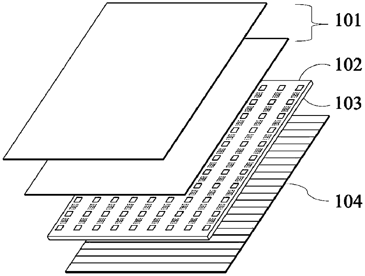
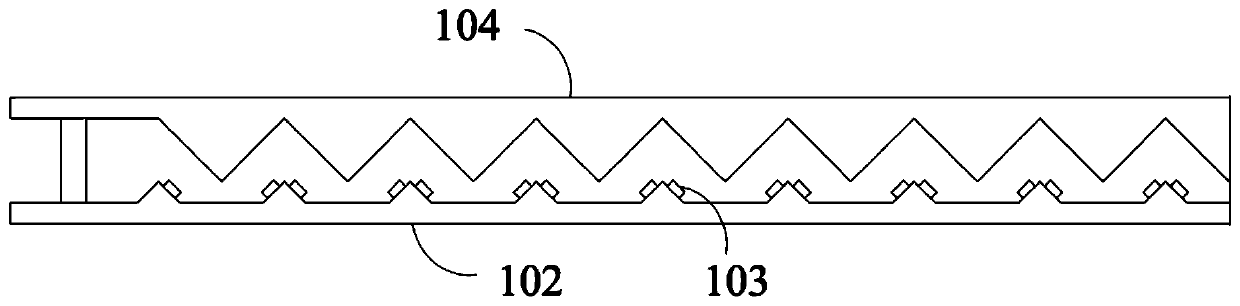
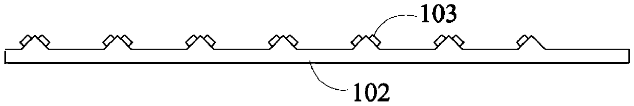
[0031] First, through Figure 1-6 , the LED backlight device according to Embodiment 1 of the present invention will be described. The LED backlight device according to Embodiment 1 of the present invention includes an optical film set 101 , a substrate 102 with an opening structure 1021 , a plurality of Mini-LED light sources 103 and an array 104 of reflective light-concentrating structures. A plurality of Mini-LED light sources 103, which are arranged on the lower surface of the substrate 102; reflective light-concentrating structure arrays 104, which are arranged below the substrate 102, for directing the light output of the Mini-LED light sources 103 to the One side of the light emitting surface of the Mini-LED backlight device is reflected and emitted through the opening structure 1021 of the substrate 102 ; the optical film group 101 is arranged above the substrate 102 . The aperture structure 1021 is arranged corresponding to the reflective light concentrating structur...

Embodiment 2

[0040] Please refer to Figure 7 , is a cross-sectional view of the reflective light-condensing structure array according to Embodiment 2 of the present invention. In the following, only the differences between Embodiment 3 and Embodiment 1 will be described, and the similarities will not be repeated here.

[0041] The reflective light-concentrating structure 1041 is a concave hemispherical structure.

Embodiment 3

[0043] In the following, only the differences between Embodiment 3 and Embodiment 1 will be described, and the similarities will not be repeated here.

[0044] The optical film set 101 also includes a quantum dot film.


PUM


Abstract

The invention discloses a backlight device of an area light source and display equipment. The LED backlight device comprises a substrate provided with an open pore structure, LED light sources arranged on the lower surface of the substrate, a reflective condensation structure arranged below the substrate and used for reflecting the light emitted by the LED light sources to one side of the light emitting surface of the LED backlight device, and an optical film group arranged above the substrate. The open pore structure is arranged corresponding to the reflective condensation structure. The invention provides the backlight device capable of improving the brightness of an axial viewing angle, and the utilization efficiency of light is improved.

Description

technical field [0001] The invention relates to a display device, in particular to an LED backlight device and a display device. Background technique [0002] With the rapid development of display technology, people's demand for displays is getting higher and higher, especially for non-planar display devices such as flexible liquid crystal displays, curved liquid crystal displays, flexible liquid crystal displays and foldable liquid crystal displays. Flexible LCD panels are about to become the mainstream in the display field due to their thinness, bendability, and impact resistance. However, the liquid crystal display device is a non-self-luminous display device, which needs to be matched with a backlight to realize display, which greatly increases the difficulty of flexible display. How to realize flexible backlighting has always been a difficult problem to solve. [0003] The direct-type backlight module is directly arranged behind the liquid crystal display panel, which...

Claims


Application Information

Patent Timeline
Patent Type & Authority Applications(China)
IPC IPC(8): G02F1/13357
CPCG02F1/133605G02F1/133606G02F1/133611G02F1/133607
Inventor 张安福李燕
Owner SHENZHEN LONGLI TECH CO LTD
Why Eureka
Try Eureka