Dielectric waveguide filter

A dielectric waveguide and filter technology, which is applied in the field of dielectric waveguide filters, can solve problems such as more zero requirements, inability to realize cross-resonator cross-coupling, and inability to realize coupling transmission zero point, etc., and achieve a simple, novel and practical structure Effect

Pending Publication Date: 2020-06-19
TONGYU COMM INC
View PDF0 Cites 3 Cited by
  • Summary
  • Abstract
  • Description
  • Claims
  • Application Information

AI Technical Summary

Problems solved by technology

[0008] Second, due to structural limitations, existing solutions cannot achieve cross-coupling between cross-resonator cavities, resulting in the inability to achieve transmission zeros with stronger coupling;
[0009] Third, for filter performance with high near-end suppression, more requirements for zero points, and asymmetrical left and right transmission zero points, such as the case where the zero point is high on the left and low on the right, and low on the left, the existing structure cannot meet the requirements

Method used


Image

  • Dielectric waveguide filter
  • Dielectric waveguide filter
  • Dielectric waveguide filter

Examples


Embodiment Construction

[0030] In order to make the purpose, technical solutions and advantages of the embodiments of the present invention clearer, the technical solutions in the embodiments of the present invention will be clearly and completely described below in conjunction with the accompanying drawings in the present invention. Obviously, the described embodiments are the Some embodiments of the invention are not all embodiments. Based on the embodiments of the present invention, all other embodiments obtained by those of ordinary skill in the art without creative efforts fall within the protection scope of the present invention.

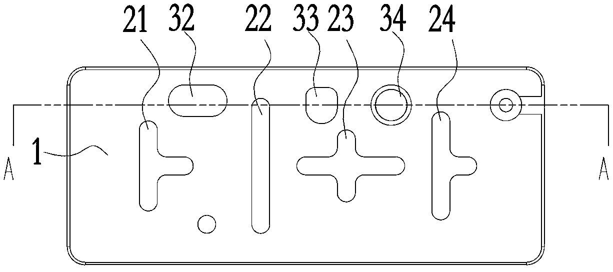
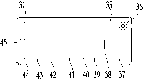
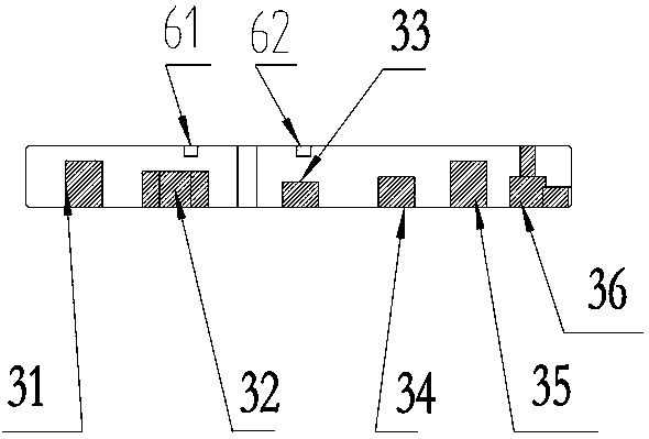
[0031] A dielectric waveguide filter, comprising a dielectric block, a resonant cavity group, an input port, an output port, and a negative coupling hole structure, the surface of the dielectric block is covered with a layer of metallic silver, and the surface on one side of the dielectric block is arranged The above input port and output port, the ceramic dielectric ...


PUM


Abstract

The invention provides a dielectric waveguide filter. The filter comprises a dielectric block, a resonant cavity group, an input port, an output port and a negative coupling hole structure, a surfaceof the dielectric block is covered with a layer of metal silver, the input port and the output port are arranged on a surface of one side of the dielectric block in parallel, a topological structure of a new negative coupling structure is adopted, and a plurality of cross coupling structures can be achieved easily through the resonant cavities which are distributed in a scattered mode. Meanwhile,the coupling structures are special-shaped groove structures which are sequentially arranged in the length direction of the dielectric block, grooves are flexibly arranged, the coupling effect betweenvarious cavities is achieved, and therefore, the filter with asymmetric left and right transmission zeros is achieved. Moreover, the coupling structures of adjacent resonant cavities can be realized,and a cross coupling structure of non-adjacent cavities can also be realized, i.e., the cross coupling between the cross resonant cavities is realized, the problem that a transmission zero point withstronger coupling cannot be realized is avoided, and the whole structure is stable and reliable.

Description

technical field [0001] The invention belongs to the technical field of filters, and in particular relates to a dielectric waveguide filter. Background technique [0002] At present, in the 5G era, limited by the requirements of Massive MIMO (large-scale antenna technology) for large-scale antenna integration, the filter needs to be more miniaturized and integrated. In the case of limited cavity size, due to the loss of its own materials, Metal coaxial cavity filters and metal cavity dielectric filters cannot achieve a high Q value, resulting in restrictions on various performance indicators. In order to meet the miniaturization requirements of 5G base station filters, ceramic dielectric filters that are easier to miniaturize have become the mainstream solution. The electromagnetic wave resonance in the ceramic dielectric filter occurs inside the dielectric material. The traditional metal cavity is replaced by a metal coating, so the volume will be smaller and the weight lig...

Claims


Application Information

Patent Timeline
Patent Type & Authority Applications(China)
IPC IPC(8): H01P1/20H01P1/208
CPCH01P1/2002H01P1/208
Inventor 高小鹏成钢方锋明彭蛟匡鹏
Owner TONGYU COMM INC
Why Eureka
Try Eureka