Automatic wiping device for aluminum alloy plate machining

An aluminum alloy plate, automatic wiping technology, applied in the field of aluminum alloy plate processing, can solve the problems of large bending degree of bristles, affecting the wiping effect, time-consuming and laborious, and prolonging the service life.

Active Publication Date: 2020-06-23
河南润鑫新材料股份有限公司
View PDF6 Cites 2 Cited by
  • Summary
  • Abstract
  • Description
  • Claims
  • Application Information

AI Technical Summary

Problems solved by technology

[0003] The object of the present invention is to provide an automatic wiping device for aluminum alloy plate processing, which has the first: when the brush head is wiping the aluminum alloy plate, it can maintain an inclined state, and then the bristles in the inclined state can press against the aluminum alloy plate After the surface of the brush, the bending degree of the bristles is relatively small, thereby prolonging the service life of the bristles on the brush head under the premise of ensuring the wiping effect; Quickly return to produce the effect of vibration and vibration, and then easily shake off the dust on the bristles of the brush head; third: the inclined surface where the bristles on the brush head contact with the surface of the aluminum alloy plate will change with the direction of displacement, thus achieving full use The effect of the bristles on the brush head solves the problem that the traditional process of wiping the surface of aluminum alloy plates generally uses manual or mechanical driving of the bristles to move back and forth. During the mechanical wiping process, the bristles are mostly perpendicular to the surface of the aluminum alloy plate and move back and forth. The bending degree of the bristles during this back and forth movement is relatively large, which in turn affects the service life of the bristles, and the bristles are in the process of wiping the aluminum alloy plate. A large amount of dust tends to accumulate on the bristles, which affects the wiping effect

Method used


Image

  • Automatic wiping device for aluminum alloy plate machining
  • Automatic wiping device for aluminum alloy plate machining
  • Automatic wiping device for aluminum alloy plate machining

Examples


Embodiment Construction

[0023] The technical solutions in the embodiments of the present invention will be clearly and completely described below in conjunction with the accompanying drawings in the embodiments of the present invention. Obviously, the described embodiments are only a part of the embodiments of the present invention, rather than all the embodiments. Based on the embodiments of the present invention, all other embodiments obtained by those of ordinary skill in the art without creative work shall fall within the protection scope of the present invention.

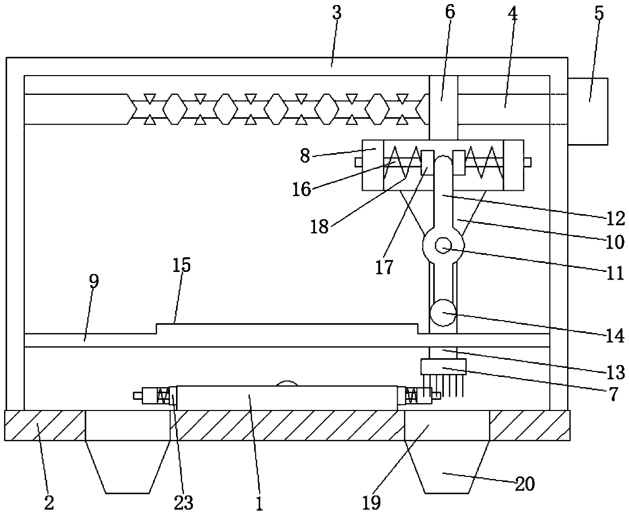
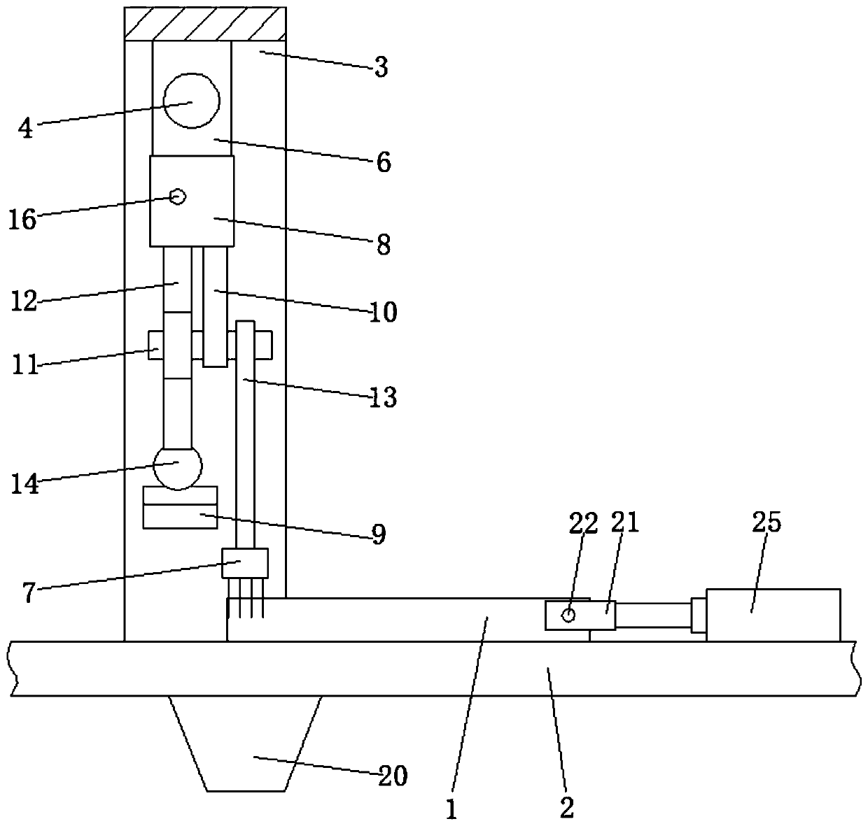
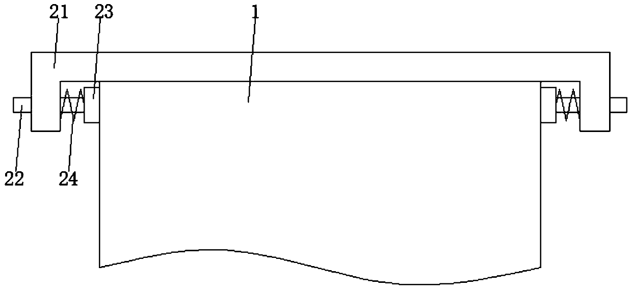
[0024] See Figure 1 to Figure 6 , The present invention provides a technical solution: an automatic wiping device for aluminum alloy plate processing, comprising an aluminum alloy plate 1 and a workbench 2. The aluminum alloy plate 1 is movably placed on the upper surface of the workbench 2, and the upper surface of the workbench 2 The surface is provided with a lateral pushing mechanism, the lateral pushing mechanism drives the aluminum...


PUM


Abstract

The invention discloses an automatic wiping device for aluminum alloy plate machining, and relates to the technical field of aluminum alloy plate machining. An aluminum alloy plate and a workbench areincluded. The aluminum alloy plate is movably placed on the upper surface of the workbench. A transverse pushing mechanism is arranged on the upper surface of the workbench and drives the aluminum alloy plate through a clamping mechanism. A supporting frame is fixedly connected to the upper surface of the workbench. The top of the supporting frame is rotationally connected with a reciprocating screw through bearing matched limiting. A motor is further fixedly arranged on the top of the supporting frame. An output shaft of the motor is fixedly connected with one end of the reciprocating screw.The outer wall of the reciprocating screw is in cup joint with a reciprocating threaded sleeve. The reciprocating threaded sleeve drives a brush head through a transmission mechanism. According to the automatic wiping device, through cooperation between above structures, the technical problems provided in the background technology are effectively solved.

Description

Technical field [0001] The invention relates to the technical field of aluminum alloy plate processing, in particular to an automatic wiping device for aluminum alloy plate processing. Background technique [0002] The aluminum alloy plate needs to enter the cleaning process before and after the processing is completed, so as to wipe off the dust on the surface of the aluminum alloy plate. The traditional surface wiping process of the aluminum alloy plate generally uses manual or mechanical driving of the bristles to move back and forth. The manual wiping process In the traditional mechanical wiping process, the bristles are mostly perpendicular to the surface of the aluminum alloy plate and move back and forth. The degree of bending of the bristles during the back and forth movement is relatively large, which will affect The service life of the bristles, and the process of wiping the aluminum alloy plate with the bristles, tends to accumulate a large amount of dust on the bristl...

Claims


Application Information

Patent Timeline
Patent Type & Authority Applications(China)
IPC IPC(8): B08B1/00B08B13/00
CPCB08B1/002B08B13/00
Inventor 任永红何小红
Owner 河南润鑫新材料股份有限公司
Why Eureka
Try Eureka