
Pole piece conveyer

A technology for conveying equipment and pole pieces, applied in conveyors, sustainable manufacturing/processing, climate sustainability, etc., can solve problems such as inconvenient adjustment of vacuum adsorption area, vacuum failure of vacuum plate, and large equipment noise, etc., to achieve adjustment The adsorption area is convenient, the effect of increasing the vacuum flow and pressure, and reducing the noise of the equipment

Pending Publication Date: 2020-06-23
深圳市阿尔斯自动化科技有限公司
View PDF0 Cites 0 Cited by
  • Summary
  • Abstract
  • Description
  • Claims
  • Application Information

AI Technical Summary

Problems solved by technology

[0002] In the field of lithium battery production, the pole piece is an important part. It is often necessary to transport the pole piece from one process to the next production process. Most of the existing transport mechanisms use ordinary vacuum adsorption mechanisms to transport the pole piece. The vacuum plate of the component is often connected to the vacuum tube from one side or from both sides by connecting the through hole of the vacuum plate to the vacuum tube. This kind of vacuum plate is prone to vacuum failure, sometimes insufficient pressure, and it is prone to inconvenient adjustment of the vacuum adsorption area. The problem of loud equipment noise

Method used


Image

  • Pole piece conveyer
  • Pole piece conveyer
  • Pole piece conveyer

Examples


Embodiment Construction

[0021] Embodiments of the present invention are described in detail below, examples of which are shown in the drawings, wherein the same or similar reference numerals designate the same or similar elements or elements having the same or similar functions throughout. The embodiments described below by referring to the figures are exemplary only for explaining the present invention and should not be construed as limiting the present invention.

[0022] If there is no special explanation, if there are words in this application that describe directions such as "up, down, bottom, top, vertical, vertical, top view, horizontal, top, bottom", they are all based on the directions shown in the drawings and cannot be understood. To limit the technical solution of the present invention.

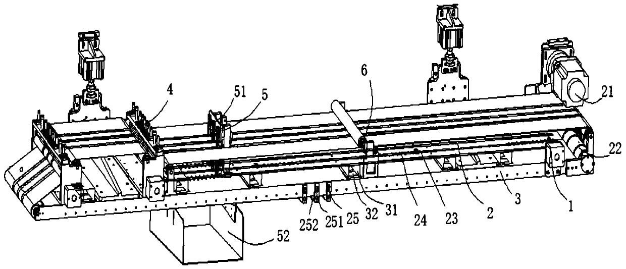
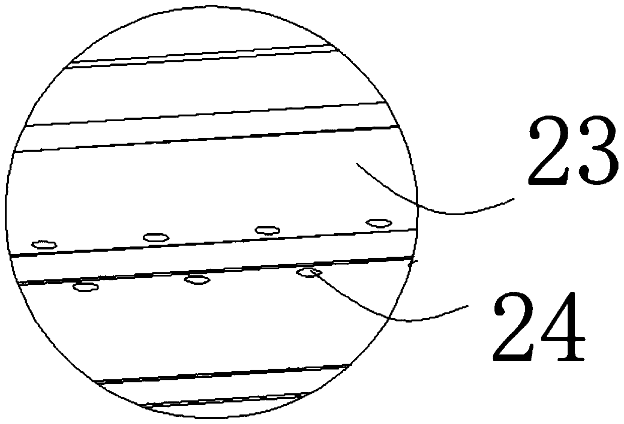
[0023] Reference attached Figure 1 to Figure 3 As shown, a pole piece conveying device according to the present invention includes a machine base 1 , a vacuum belt assembly 2 set on the machine base 1 ...


PUM


Abstract

The invention discloses a pole piece conveyer which comprises a machine station, a vacuum belt component arranged on the machine station and capable of driving, and a vacuum mechanism arranged on themachine station, wherein the vacuum belt component is cooperated with the vacuum mechanism to generate vacuum adsorption force; the vacuum mechanism comprises a plurality of vacuum cavities formed inthe machine station at intervals, and a plurality of vacuum draught hoods cooperated with the vacuum cavities correspondingly; a vacuum suction opening is formed in each of the vacuum cavities; and the vacuum draught hoods are correspondingly arranged on the vacuum cavities and communicate with the interiors of the vacuum cavities via the vacuum suction openings. The pole piece conveyer can reducethe power of a vacuumizing fan to further realize the purposes of saving energy and lowering equipment noise, can more conveniently adjust the vacuum adsorption area as demanded and increases the integral vacuum flow rate and pressure.

Description

technical field [0001] The invention belongs to the technical field of lithium battery production, and in particular relates to a pole piece conveying device. Background technique [0002] In the field of lithium battery production, the pole piece is an important part. It is often necessary to transport the pole piece from one process to the next production process. Most of the existing transport mechanisms use ordinary vacuum adsorption mechanisms to transport the pole piece. The vacuum plate of the component is often connected to the vacuum tube from one side or from both sides by connecting the through hole of the vacuum plate to the vacuum tube. This kind of vacuum plate is prone to vacuum failure, sometimes insufficient pressure, and it is prone to inconvenient adjustment of the vacuum adsorption area. The problem of loud equipment noise. Contents of the invention [0003] The present invention aims to solve at least one of the technical problems existing in the prio...

Claims


Application Information

Patent Timeline
Patent Type & Authority Applications(China)
IPC IPC(8): B65G15/58H01M10/058
CPCB65G15/58H01M10/058B65G2201/022Y02E60/10Y02P70/50
Inventor 饶卫景丁幼祥
Owner 深圳市阿尔斯自动化科技有限公司
Learn More