
Control method for elevation angle flange lifting during heavy equipment transportation

A control method and technology for heavy equipment, applied in the direction of hoisting devices, hoisting devices, etc., can solve the problems of poor applicability and flexibility, equipment auxiliary transportation, and high cost of use, and achieve the goal of improving motion ability, bottom moment, and friction Effect

Active Publication Date: 2020-06-23
蒙阴县鹏程万里车辆有限公司
View PDF9 Cites 0 Cited by
  • Summary
  • Abstract
  • Description
  • Claims
  • Application Information

AI Technical Summary

Problems solved by technology

[0007] To sum up, the present invention provides an elevation angle lifting device for transporting heavy equipment. Through structural and functional improvements, the structure is fixed, and the applicability and flexibility are poor. It needs to cooperate with cranes and other equipment to adjust the elevation angle. The cost is high, and the problem that it cannot be directly used as a carrier for auxiliary transportation of equipment

Method used

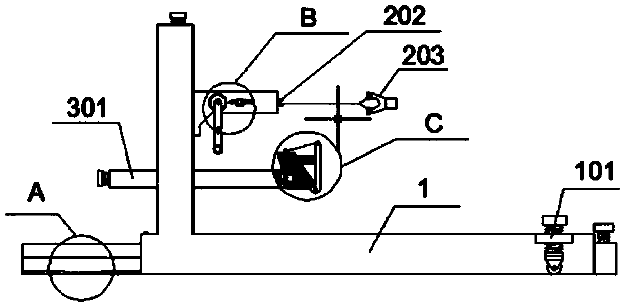
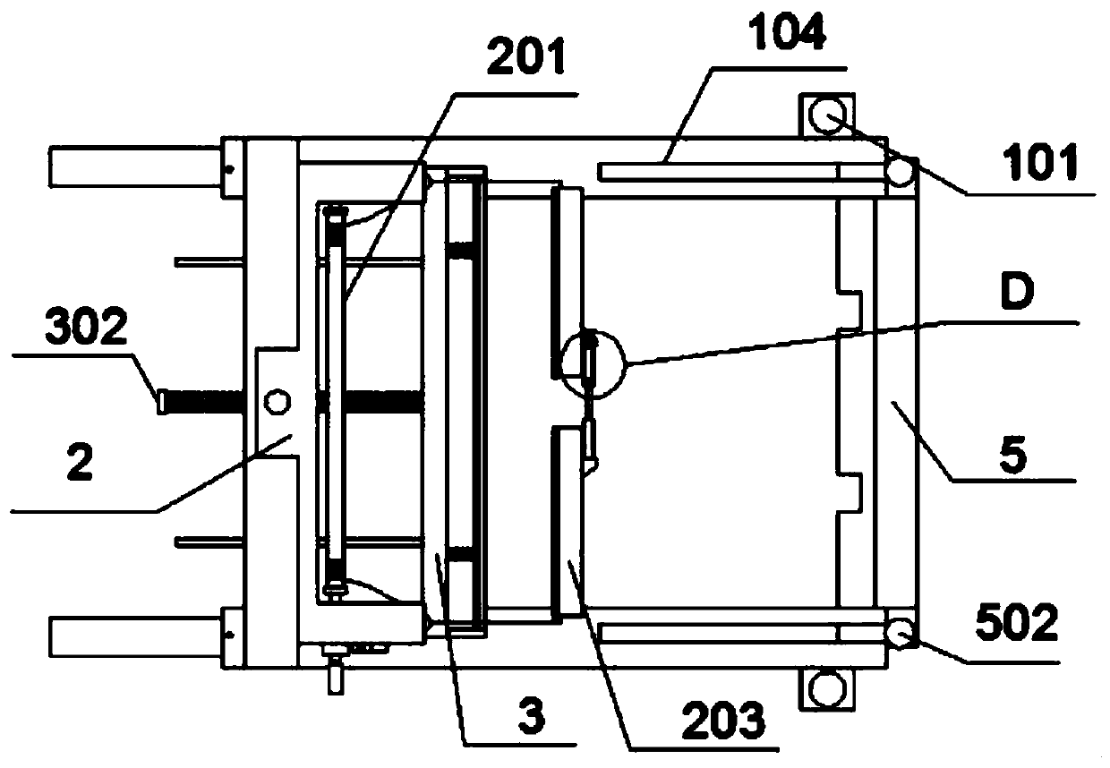
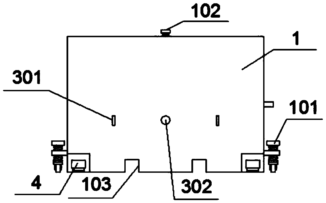

Image

  • Control method for elevation angle flange lifting during heavy equipment transportation
  • Control method for elevation angle flange lifting during heavy equipment transportation
  • Control method for elevation angle flange lifting during heavy equipment transportation

Examples


Embodiment Construction

[0033] Embodiments of the present invention will be further described in detail below in conjunction with the accompanying drawings and examples. The following examples are used to illustrate the present invention, but should not be used to limit the scope of the present invention.

[0034] In the description of the present invention, unless otherwise stated, the meaning of "plurality" is two or more; the terms "upper", "lower", "left", "right", "inner", "outer" , "front end", "rear end", "head", "tail", etc. indicate the orientation or positional relationship based on the orientation or positional relationship shown in the drawings, and are only for the convenience of describing the present invention and simplifying the description, rather than Nothing indicating or implying that a referenced device or element must have a particular orientation, be constructed, and operate in a particular orientation should therefore not be construed as limiting the invention. In addition, t...


PUM


Abstract

The invention provides a control method for elevation angle flange lifting during heavy equipment transportation. The control method is implemented on the basis of an elevation angle flange lifting device. The elevation angle flange lifting device comprises a rack, auxiliary universal wheels, a lifting bolt, a main forklift hole, a Y-shaped hook block, a push plate, an auxiliary sliding plate, ananti-skid rubber blanket, a bottom lifting plate, an auxiliary forklift hole and a locking screw. The outer ends of the two sides of the bottom of the rack are fixedly provided with two sets of auxiliary universal wheels through bolts. The auxiliary universal wheels can lift the height through a rotating bolt. A square groove is formed in one side of the top of the rack, a round hole is formed inthe middle of the top of the square groove, and a bearing is embedded into the round hole. By arranging the Y-shaped hook block and the push plate, elevation angle flange lifting can be performed on flat bottom equipment, the bottom of the equipment can be lifted conveniently, and the flat bottom type equipment can be transported and moved conveniently. By arranging a stretchable rock rod, the motion capability of the elevation angle flange lifting device is effectively improved, the torque can be increased by stretching the stretchable rock rod, and manual bottom lifting can be performed conveniently.

Description

[0001] This application is a divisional application of the Chinese invention patent application with the application number 201811277222.2 filed on October 30, 2018, and the title of the invention is an elevation angle lifting device for transporting heavy equipment. technical field [0002] The present invention relates to the technical field of transportation facilities, and more specifically, to a method for controlling elevation angle lifting when transporting heavy equipment. Background technique [0003] Commonly used medium-sized and large-scale equipment usually has a relatively heavy mass. In order to improve the structure such as waterproof and dustproof, the shape of the bottom of the equipment is gradually changed, and the bottom of the equipment is designed as a flat structure, which saves the cumbersome processing and transportation structure and saves costs. However, the structure of the flat bottom surface is not convenient for transportation, and it is necess...

Claims


Application Information

Patent Timeline
Patent Type & Authority Applications(China)
IPC IPC(8): B66F19/00
CPCB66F19/00
Inventor 杨佳魏
Owner 蒙阴县鹏程万里车辆有限公司
Learn More